Adjustable positioning structure for pre-buried bolt double-layered positioning plate and construction method

A technology for pre-embedded bolts and positioning structures, which is applied in basic structure engineering, building construction, construction, etc., can solve the problem that the location accuracy of pre-embedded bolts and the 100% quality pass rate cannot be guaranteed. Low efficiency and other problems, to achieve the effect of being conducive to process quality control, ensuring installation accuracy, and avoiding rework

Active Publication Date: 2013-11-20
ZHONGTIAN CONSTR GROUP +1
View PDF7 Cites 14 Cited by
  • Summary
  • Abstract
  • Description
  • Claims
  • Application Information

AI Technical Summary

Problems solved by technology

This method is difficult to guarantee the quality of the post-cast concrete or grouting, and the post-cast concrete or grouting and the original concrete are prone to cracks, which affects the overall durability of the structure, and the construction efficiency of this method is low
[0005] (3) Pre-embedding method of positioning formwork: the upper part of the bolt is fixed on the foundation formwork with square wood or positioning formwork, and the lower part is fixed with steel bars and welded. This pre-embedding method is not strong in adjustability and integrity, and cannot be guaranteed Relative positional accuracy of embedded bolts
The above four methods (ordinary direct burial method, bolt back burial method, positioning formwork pre-embedding method, upper and lower positioning plate support frame fixed pre-embedding method) cannot guarantee the position accuracy of the pre-embedded bolts and 100% quality pass rate to meet the requirements at the same time. On-site construction feasibility

Method used


Image

  • Adjustable positioning structure for pre-buried bolt double-layered positioning plate and construction method
  • Adjustable positioning structure for pre-buried bolt double-layered positioning plate and construction method
  • Adjustable positioning structure for pre-buried bolt double-layered positioning plate and construction method

Examples


Embodiment Construction

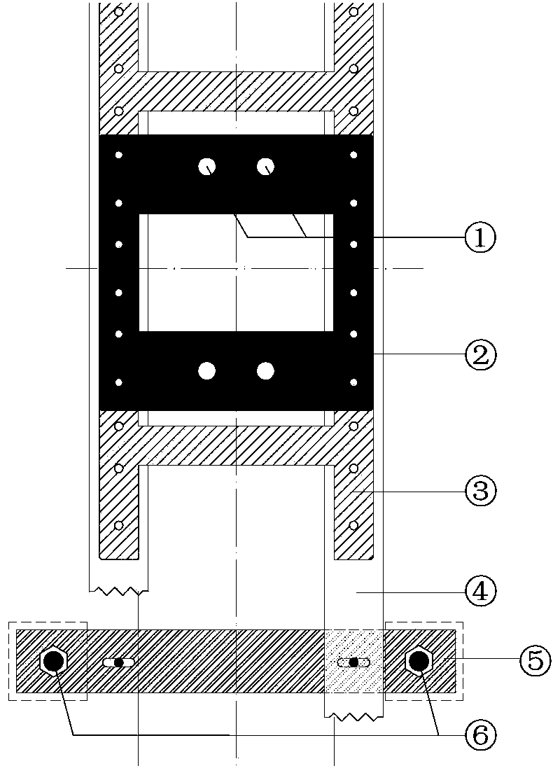
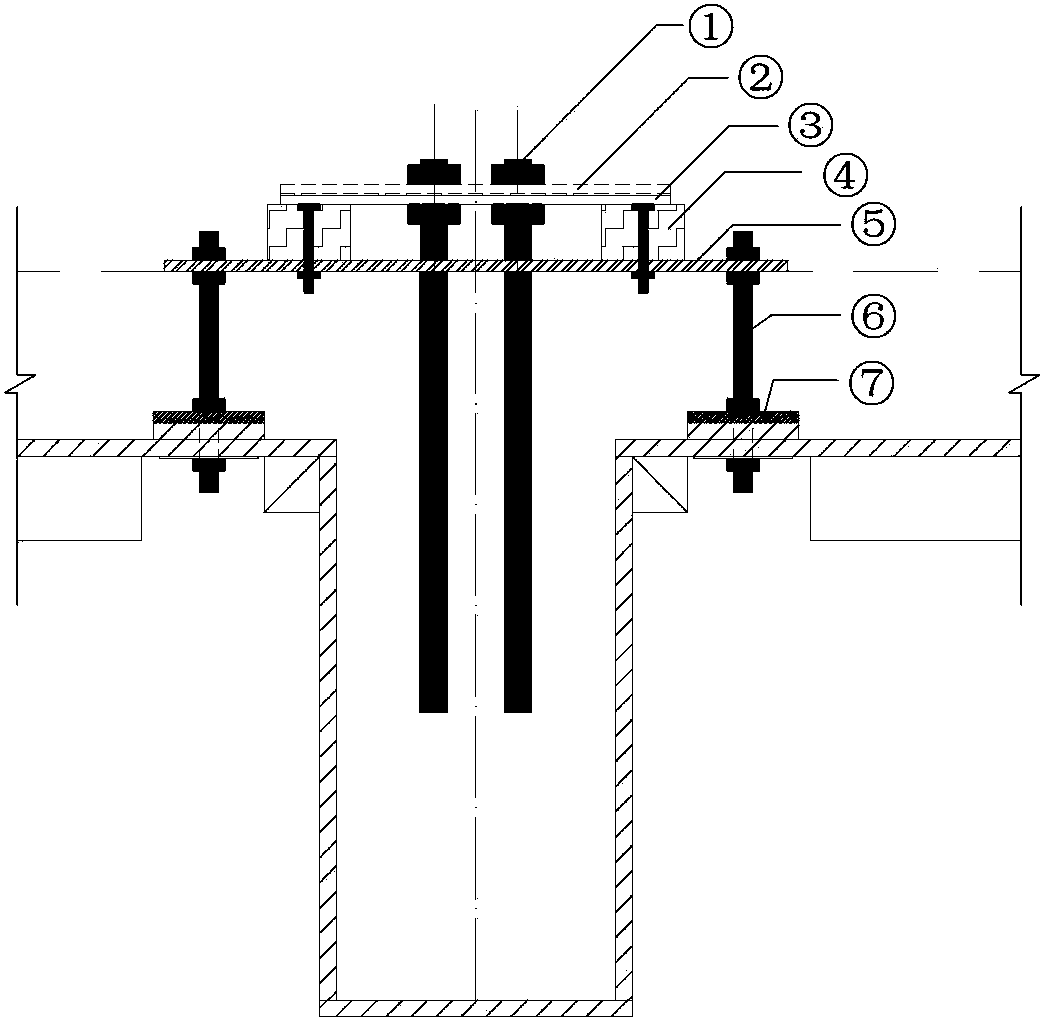
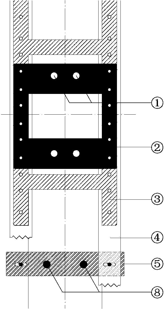
[0031] combine first Figure 1 to Figure 5 The specific structure of the adjustable positioning structure of the embedded bolt double-layer positioning plate is explained: it includes four additional embedded bolts arranged vertically on the four corners of a rectangle (M16 additional embedded bolts 6 on the beam, and 6 on the wall) M24 additional embedded bolts 8), additional iron plates 5 are arranged on the front and rear sides of the rectangle, the two ends of the additional iron plates 5 and the upper ends of the additional embedded bolts are fixed by nuts, and the additional iron plates adjust the elevation and Horizontal, two wooden squares 4 are arranged in parallel between the two additional iron plates, the additional iron plates are provided with position adjustment holes, and the wooden squares 4 are fixed with the additional iron plates through bolts and position adjustment holes To adjust the lateral position, a full-length positioning plate 3 with a frame struct...


PUM


Abstract

The invention discloses an adjustable positioning structure for a pre-buried bolt double-layered positioning plate and a construction method. The structure comprises four additional pre-buried bolts vertically arranged at the four corners of a rectangle, wherein additional iron plates are arranged on the front side edge and the back side edge of the rectangle; two wood beams are parallelly arranged between the two additional iron plates; position adjusting holes are formed in the additional iron plates; a michinaga positioning plate adopting a frame structure is mounted on the wood beams; a socle positioning plate is mounted on the michinaga positioning plate in a hanging manner; socle pre-buried bolts are mounted on the socle positioning plate. During the whole process of mounting the adjustable positioning structure for the double-layered positioning plate, the mounting of each step is adjustable, the process quality control is facilitated, the mounting precision of pre-buried bolts is ensured, and the reworking is avoided. Through the practical application on the construction site, and through the adoption of the adjustable positioning structure for the double-layered positioning plate provided by the invention to carry out the construction of the pre-buried bolts, the allowable deviation of the pre-buried bolts in a practical project is larger than the national regulation requirement.

Description

technical field [0001] The invention relates to the pre-embedded construction technology of pre-embedded bolts at the foot of steel columns of construction engineering, or the pre-embedded construction technology of pre-embedded bolts on equipment foundations. Background technique [0002] The pre-embedded construction of pre-embedded bolts is a common construction content in construction engineering, and there are many pre-embedded methods. Several common bolt pre-embedded methods and their advantages and disadvantages are as follows: [0003] (1) Ordinary direct burial method: the pre-embedded bolts are directly fixed to the steel bars before pouring concrete, and the bolts are fixed after the concrete pouring is completed. In this method, the pre-embedded bolts are prone to deviation during the concrete pouring process, and the deviation generated after the concrete pouring cannot be adjusted, which will seriously affect the subsequent construction, cause a lot of rework,...

Claims


Application Information

Patent Timeline
Patent Type & Authority Applications(China)
IPC IPC(8): E04B1/41E02D27/44E04G21/00
Inventor 孙鸿恩俞洪元韩正恳张俊陆建飞
Owner ZHONGTIAN CONSTR GROUP
Why Eureka
Try Eureka