
Optical fiber grating temperature measuring device and measuring method

A fiber grating, temperature measurement technology, applied in the direction of measuring device, measuring heat, using optical device to transmit sensing components, etc., can solve the problems of fiber grating manufacturing error, low system reliability, temperature measurement error, etc., to improve system reliability. The effect of stability, easy system networking, and long transmission distance

Active Publication Date: 2013-11-20
8TH RES INST OF CETC
View PDF5 Cites 13 Cited by
  • Summary
  • Abstract
  • Description
  • Claims
  • Application Information

AI Technical Summary

Problems solved by technology

[0005] The grating array structure of the above-mentioned distributed fiber grating temperature detection system is linear, that is, the fiber grating is arranged in series along the optical fiber. There may be large errors in temperature measurement, and the system reliability is low

Method used


Image

  • Optical fiber grating temperature measuring device and measuring method
  • Optical fiber grating temperature measuring device and measuring method

Examples

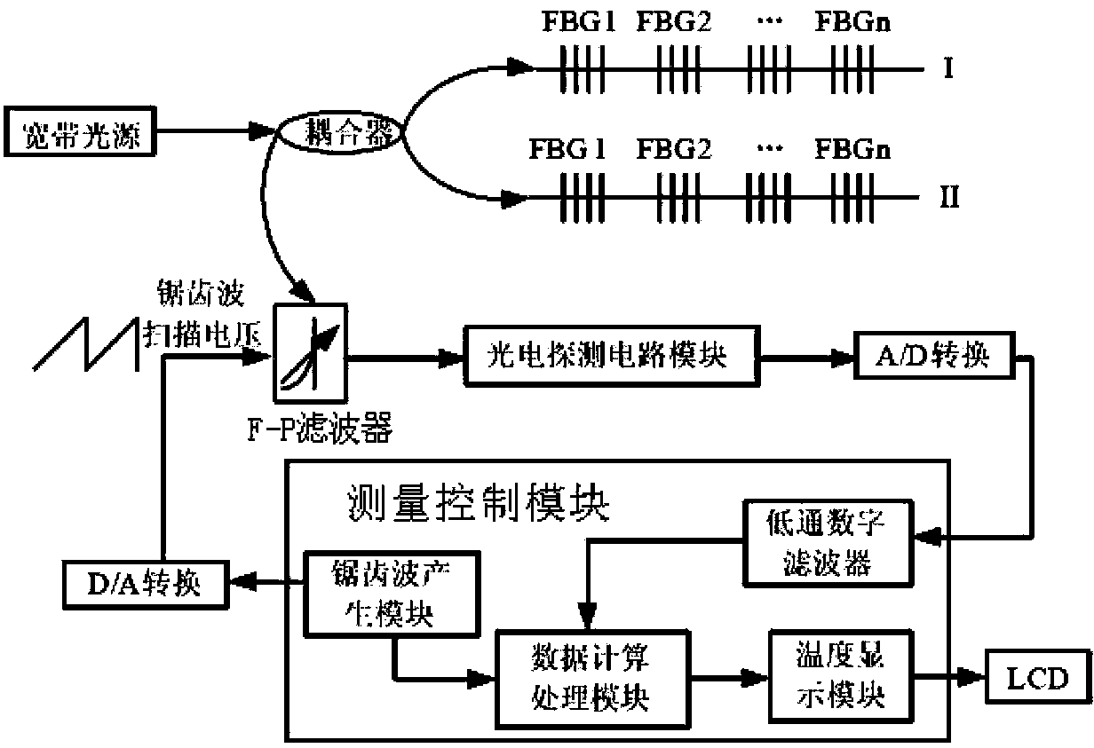

Embodiment Construction

[0024] In order to make the technical problems, technical solutions and beneficial effects to be solved by the present invention clearer, the present invention will be further described in detail below in conjunction with the accompanying drawings and embodiments. It should be understood that the specific embodiments described here are only used to explain the present invention, and It is not a limitation of the invention.

[0025] figure 1 is a schematic structural view of a fiber grating temperature measuring device according to an embodiment of the present invention, figure 1 Among them, the broadband light source is optically connected to one branch port of the fiber coupler, and the other branch port of the fiber coupler is optically connected to the input port of the optical detection circuit module through a tunable fiber filter, and the output of the fiber coupler is divided into two , enters two series sensing fiber grating arrays through the optical fiber, the tunab...


PUM


Abstract

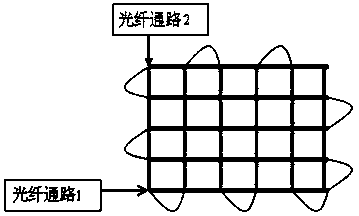
An optical fiber grating temperature measuring device comprises a broadband light source, an optical fiber coupler, a tunable optical fiber filter, an optical fiber, an optical fiber grating sensor, an optical detection circuit module and a measurement control module, wherein the output of the optical fiber coupler can be divided into two ways, the two ways enter into two sensor optical fiber grating arrays connected in series through optical fibers, one of the sensor optical fiber grating array comprises a plurality of horizontally arranged optical fiber gratings, the other sensor optical fiber grating array comprises a plurality of vertically arranged optical fiber gratings, the horizontally arranged optical fiber gratings and the vertically arranged optical gratings are interlapped in space, so as to form a rasterized optical fiber grating. Through the adoption of the variable grating, real time temperature change of any lattice point in the area can be obtained, and through the parameter self-correcting comparison, and mean value, network node redundancy, reliability of the system is improved.

Description

technical field [0001] The invention relates to a temperature measurement system, in particular to a fiber grating temperature measurement system. Background technique [0002] In order to realize the monitoring of a dynamic temperature point on the surface of the photoelectric integrated cable, the temperature must be monitored in the cylindrical area where the dynamic temperature point is located. The traditional temperature measurement methods include thermocouples, infrared thermometers, etc. Thermocouples have a limited transmission distance and cannot achieve long-distance transmission. The signal drifts a lot and needs to be calibrated regularly. Because it belongs to point measurement, it can only monitor the temperature point, and cannot realize the temperature monitoring of the area. To realize the monitoring of the entire cylindrical area, multiple points can only be arranged one by one and fill the cylindrical surface area. All sensitive resistors need to be wir...

Claims


Application Information

Patent Timeline
IPC IPC(8): G01K11/32G01D5/353G01K11/3206
Inventor 陆兆辉
Owner 8TH RES INST OF CETC
Learn More