Electrical compensation of optical impairments

a technology of optical impairment and electric compensation, applied in the direction of optical transmission, electrical apparatus, electromagnetic transmission, etc., can solve the problems of chromatic dispersion, optical signal distortion, and high cost, and achieve the effect of reducing impairment and low cos

Active Publication Date: 2007-06-21
CIENA
View PDF5 Cites 29 Cited by
  • Summary
  • Abstract
  • Description
  • Claims
  • Application Information

AI Technical Summary

Benefits of technology

[0007] According to a first aspect of the invention, there is provided a pre-distortion unit for compensating optical transmission impairments of a communications signal conveyed through an optical communications system comprising: at least one electrical filter for modifying an electrical input signal using a pre-distortion function to generate a pre-distorted electrical signal which mitigates the impairments in an optical system; and at least one upconverter for modulating the pre-distorted electrical signal onto an electrical carrier signal for modulation of an optical signal to generate

Problems solved by technology

One impairment the optical fibre may exhibit is chromatic dispersion.
This results in the optical signal being distorted.
However, there are a number of drawbacks to using dispersion compensating fibre modules for compensating for the optical dispersion.
The most obvious disadvantage is that they tend to be very costly.
However, they are also relatively large and have high optical loss.
This latter feature results in more optical amplification being required which in turn increases cost and can have degrading effect on performance.
A further disadvantage is that dispersion compensating fibre modules tend to be more sensitive to nonlinear distortion, thus also reducing performance.
Such a modulator is considera

Method used


Image

  • Electrical compensation of optical impairments
  • Electrical compensation of optical impairments
  • Electrical compensation of optical impairments

Examples


first embodiment

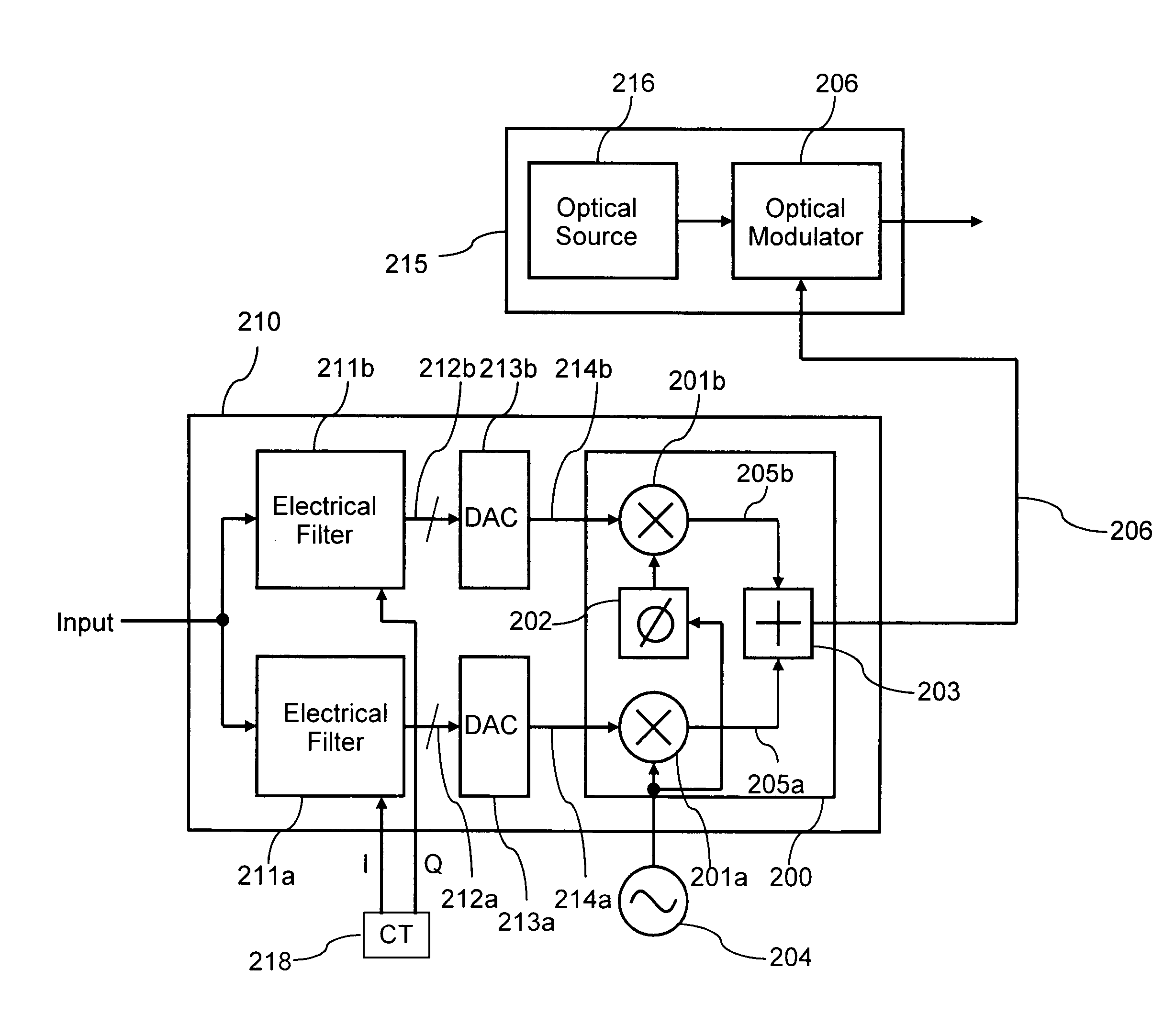
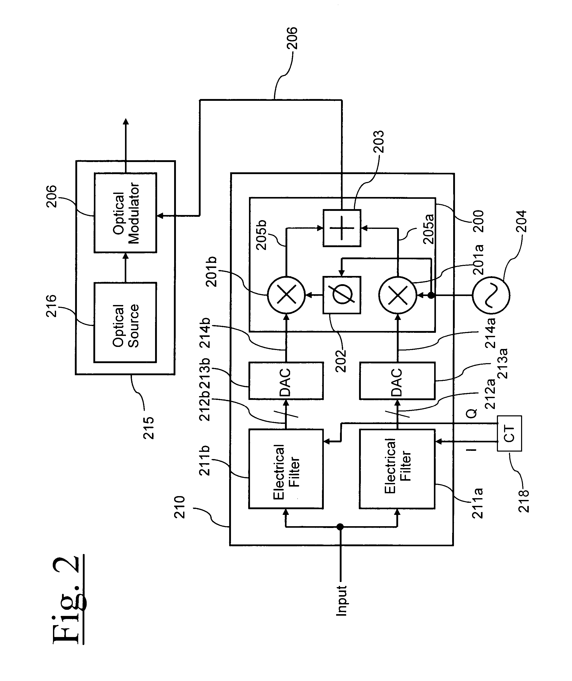
[0035]FIG. 2 shows a schematic block diagram in accordance with the present invention. Here there is an optical transmitter 215 comprising an optical source 216 (which may be a semiconductor laser and may be wavelength tunable) and an optical modulator 206. The optical modulator 206 is different from the complex optical modulator 217 in that it only takes a single input 206 and can therefore not modulate the amplitude and phase of an optical signal independently. This modulator 206 may be an electroabsorption modulator with a single electrical input. The modulator 206 may be monolithically integrated on the same substrate as the optical source. The information to be transmitted is coupled to a different electrical pre-distortion unit 210 comprising two paths to generate the I 214a and Q 214b signal components of the pre-distorted signal. The two paths each comprise an electrical filter 211a and 211b, which may be digital filters, a serial to parallel converter 212a and 212b and a di...

second embodiment

[0041]FIG. 5 shows the present invention in which there is an optical transmitter 215 and an optical pre-distortion unit 210. Here there are two paths and two electrical filters 211a and 211b, taking additional inputs from the I and Q components of the pre-distortion transfer function respectively. In this embodiment, these digital signals are directly fed into the upconverter unit 200, which is now implemented in a digital form. The output from the upconverter unit is then a single digital signal which is coupled to a serial to parallel converter 212 and a digital to analogue converter 213. This configuration has the advantage that more of the processing is performed digitally for greater fidelity and only a single digital to analogue converter is required. However this digital to analogue converter must have a wider bandwidth.

third embodiment

[0042]FIG. 6 shows a third embodiment in which a direct detection receiver is used instead of a coherent receiver. Here there is also an optical transmitter 215, a pre-distortion unit 210 an optical link 300 and a receiver 301. However in this instance instead of removing the unwanted sideband 401 by an electrical filtering means, an optical filtering means is used 500. This filter may positioned anywhere within the optical part of the system, e.g. before, after or within the optical link 300. The optical filtering means may be positioned within the optical transmitter 215 and may also be combined within an optical element used for establishing the wavelength of the optical source. Typically a laser package would incorporate an optical filter on the rear facet for monitoring its wavelength. By moving this element to the front facet, the element would perform the dual functions of wavelength monitoring and unwanted sideband removal. The optical filter 500 may instead be incorporated ...


PUM


Abstract

Optical impairments such as dispersion and fibre nonlinearity are compensated by generating a pre-distorted electrical signal at the transmitter. This signal is modulated onto a carrier signal, so that it is upconverted in frequency. This up converted signal is then used to modulate an optical source. Generally the optical signal will have two sidebands, one of which has the correctly pre-distorted information and the other which is unwanted. Information in the unwanted optical sideband is either filtered optically or electrically. In the preferred embodiments, the transmitter uses a tunable semiconductor laser with an integrated electroabsorption modulator to modulate the light. The preferred receiver is a coherent receiver with a tunable local oscillator laser. The receiver uses an electrical filter to remove the information in the unwanted sideband.

Description

FIELD OF THE INVENTION [0001] The present invention relates to a method and apparatus for compensating for optical impairments electrically and a system incorporating the same. BACKGROUND TO THE INVENTION [0002] Optical communications systems typically comprise of a transmitter which converts electrical signals into optical signals, an optical link over which the optical signals are transported and a receiver which converts the optical signal into an electrical signal, the electrical signal recovered at the receiver ideally being identical to the electrical signal originating at the transmitter. The optical link generally consists of optical transmission fibre to convey the signal and optical amplifiers to compensate for the loss that the fibre introduces. The optical amplifiers are generally interspersed at regular intervals along the link (e.g. every 40-200 km). [0003] One impairment the optical fibre may exhibit is chromatic dispersion. This is where different optical frequencies...

Claims


Application Information

Patent Timeline
IPC IPC(8): H04B10/00H04B10/58
CPCH04B10/58H04B2210/254
Inventor FELLS, JULIAN
Owner CIENA
Why Eureka
Try Eureka