Ejector pin type integrated circuit testing fixture

A technology for integrated circuits and test fixtures, applied in the field of fixtures, can solve problems such as the influence of test results and the generation of static electricity on the chip, and achieve the effects of uniform force, large use range and consistent use methods

Inactive Publication Date: 2013-11-20
TWINSOLUTION TECH
View PDF7 Cites 9 Cited by
  • Summary
  • Abstract
  • Description
  • Claims
  • Application Information

AI Technical Summary

Problems solved by technology

[0006] In addition, the chip will generate static electricity during the test process, which will affect the test results

Method used


Image

  • Ejector pin type integrated circuit testing fixture
  • Ejector pin type integrated circuit testing fixture
  • Ejector pin type integrated circuit testing fixture

Examples


Embodiment Construction

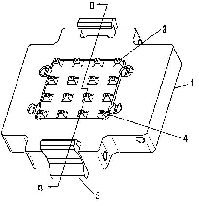
[0037] Figure 1~Figure 4 As described above, a thimble-type integrated circuit test fixture is composed of the following components: a cover body 1, a hook 2, a pressure plate 3, a thimble 4, a first spring 6, a cover plate 7, a second spring 8 and a hook spring 9.

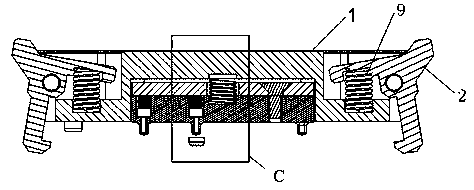
[0038] Grab hook 2 is installed on cover main body 1 both sides, by grab hook spring 9 and locating pin, grab can open and close freely, and grab is used for connecting jig cover and jig base.

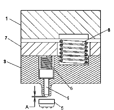
[0039] The thimble 4 is vertically embedded in the needle cavity of the pressure plate 3, the first spring 6, the cover plate 7, the pressure plate 3 and the thimble 4 are fastened by screw fasteners to form a thimble mechanism, and the thimble mechanism is installed in the inner cavity of the cover main body 1.

[0040] The thimble 4 is stepped, the first spring 6 is arranged between the cover plate 7 and the thimble 4, the thimble 4 is fixed in the pressure plate 3 under the spring force of the first spring 6, the pres...


PUM


Abstract

The invention relates to an ejector pin type integrated circuit testing fixture. The ejector pin type integrated circuit testing fixture consists of a cover main body, clamping hooks, pressure plates, ejector pins, first springs, cover plates, second springs and clamping hook springs, wherein the cover plates, the pressure plates, the first springs and the ejector pins 4 are fastened into an ejector pin mechanism through fastening parts; the ejector pin mechanism is arranged in an inner cavity of the cover main body; the ejector pins are stepped; the first springs are arranged between the cover plates and the ejector pins; the ejector pins are fixedly arranged in the pressure plates under the action of spring force of the first springs; the first springs and the ejector pins can freely move up and down in the inner cavity; through holes are formed in the pressure plates; one end of each ejector pin penetrates through the through hole of the corresponding pressure plate, and is raised from the bottom surface of the corresponding pressure plate; and the pinheads of the ejector pins are raised from the planes of the pressure plates in an untested state. According to the ejector pin type integrated circuit testing fixture, the magnitude of force applied to chips can be controlled through the ejector pin mechanism by regulating the amounts of compression of the springs, and damage to the chips is avoided.

Description

technical field [0001] The invention is a jig used for semiconductor chip testing. Background technique [0002] The current technology and development trend of electronic packaging is to have higher electrical and thermal properties, light, thin, small, mass production, easy installation, use, and rework characteristics. The miniaturization and high-density packaging of devices is becoming more and more More, such as Wafer Level Chip Scale Packaging (WLCSP for short), MEMS, Micro-Electro-Mechanic System, Multi-Module Package (MCM), System in Package (SiP), inverted There are more and more applications such as mounting chips (FC, Flip-Chip). The emergence of these high characteristics puts forward higher and newer requirements for chip test fixtures. [0003] Traditional test fixtures such as Figure 6 As shown, its working principle is: put the IC into the test socket, and the pressure plate on the test cover is directly pressed or spun on the top of the chip to ensure th...

Claims


Application Information

Patent Timeline
Patent Type & Authority Applications(China)
IPC IPC(8): G01R31/28
Inventor 高宗英田治峰贺涛高凯王强殷岚勇
Owner TWINSOLUTION TECH
Why Eureka
Try Eureka