Method for achieving crystal oscillator dual redundancy in flight control computer

A flight control computer, dual-redundancy technology, applied to hardware redundancy for error detection of data, generation of response errors, etc., can solve problems such as unusable and reduced reliability of the flight control computer clock, and improve reliability performance, improve efficiency and convenience, and have strong versatility

Active Publication Date: 2013-11-20
BEIJING AEROSPACE AUTOMATIC CONTROL RES INST +1
View PDF4 Cites 11 Cited by
  • Summary
  • Abstract
  • Description
  • Claims
  • Application Information

AI Technical Summary

Problems solved by technology

[0003] The above two crystal oscillator access methods have a common fatal flaw: if any crystal oscillator stops vibrating, the DSP or FPGA will stop working, and then the flight control computer composed of DSP+FPGA architecture will be unusable, and the crystal oscillator stops vibrating. It is the main failure mode of the crystal oscillator (the failure rate is as high as 80%), so the above two access methods of the crystal oscillator greatly reduce the reliability of the flight control computer clock.

Method used


Image

  • Method for achieving crystal oscillator dual redundancy in flight control computer
  • Method for achieving crystal oscillator dual redundancy in flight control computer
  • Method for achieving crystal oscillator dual redundancy in flight control computer

Examples


Embodiment Construction

[0020] Specific embodiments of the present invention will be further described in detail below in conjunction with the accompanying drawings.

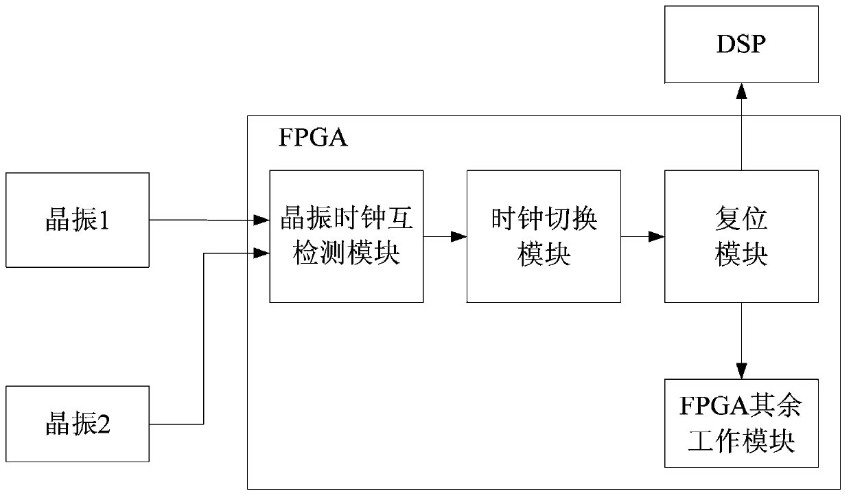
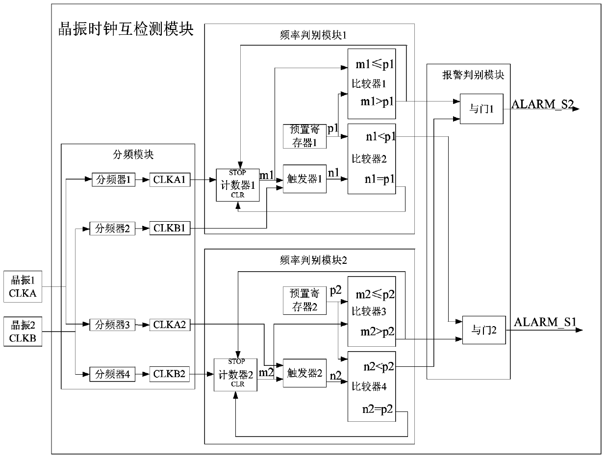
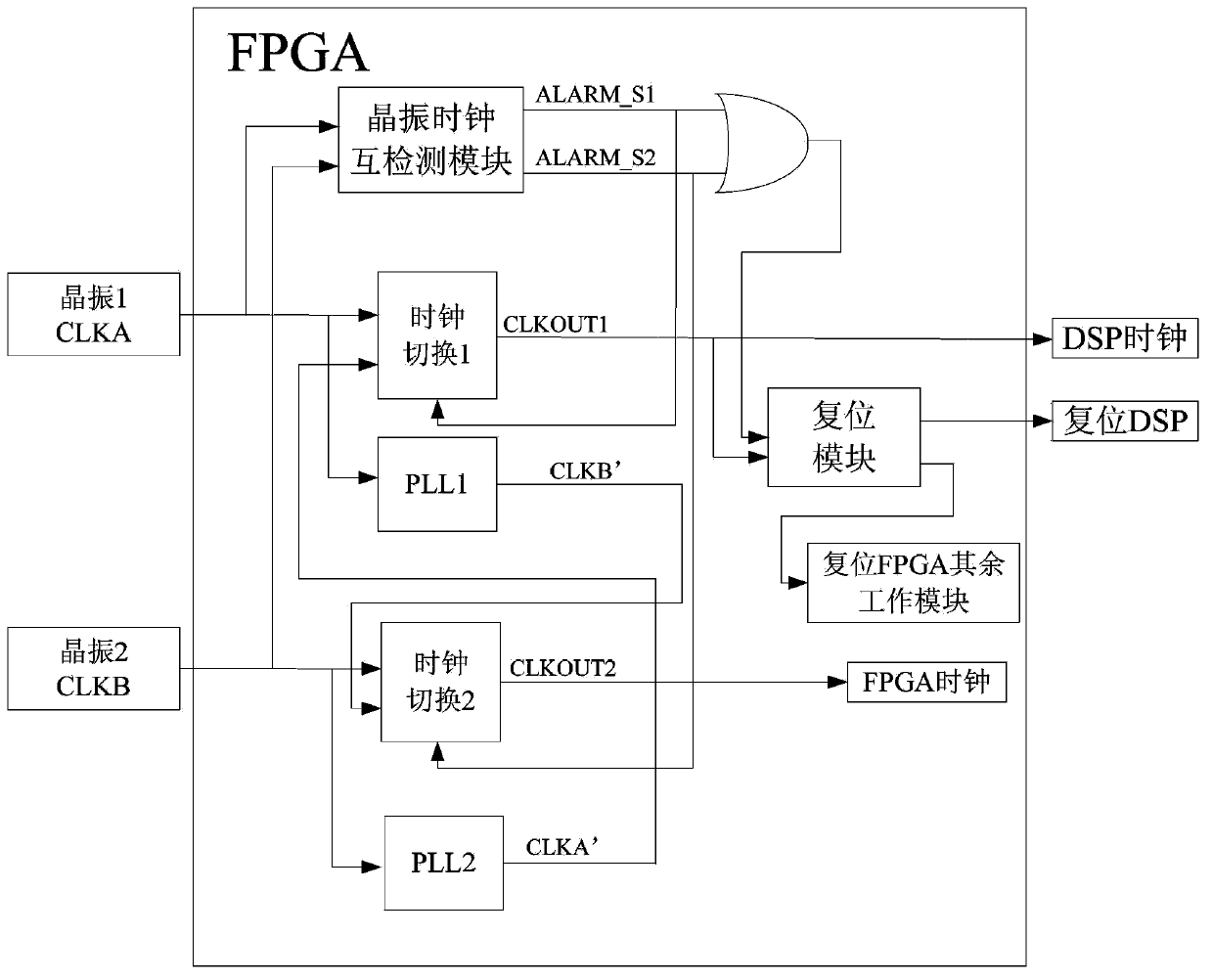
[0021] The present invention provides a method for realizing dual redundancy of crystal oscillators in the flight control computer, which realizes that when any one crystal oscillator stops vibrating, the other crystal oscillator simultaneously provides a reliable and stable clock signal for DSP and FPGA, ensuring the accuracy of the clock used by the flight control computer. high reliability. Such as figure 1 As shown, the present invention is mainly composed of the following modules: dual crystal oscillators, FPGA, and DSP, wherein the FPGA includes a crystal oscillator clock mutual detection module, a clock switching module, and a reset module. The dual crystal oscillator sends the clock signal to the FPGA, and uses the FPGA crystal oscillator clock mutual detection module to perform mutual detection of the frequency of the dual cr...


PUM


Abstract

The invention provides a method for achieving crystal oscillator dual redundancy in a flight control computer. The flight control computer comprises two crystal oscillators, an FPGA and a DSP. The method includes the steps that a dual-crystal-oscillator clock is sent to the FPGA, and the frequency of the dual-crystal-oscillator clock is detected through an FPGA crystal oscillator clock mutual-detection module, the two crystal oscillators supply clock signals for the DSP and the FPGA respectively if both the two crystal oscillators normally work, when oscillation stop occurs to either one of the crystal oscillators, a clock switching module is started, the other crystal oscillator simultaneously supplies clock signals for the DSP and the FPGA, and meanwhile a reset module is started to supply reset signals for the DSP and the FPGA. The mutual detection conducted for finding out whether oscillation stop occurs to the dual-crystal-oscillator clock or not is achieved. When oscillation stop occurs to either one of the crystal oscillators, the other single crystal oscillator simultaneously supplies the reliable clock signals for the DSP and the FPGA through the clock switching module, and reliability of using the clock of the flight control computer can be effectively improved through the whole crystal oscillator dual redundancy design method.

Description

technical field [0001] The invention relates to a method for realizing double redundancy of crystal oscillators in a flight control computer, which is suitable for the high reliability design field of the flight control computer clock based on DSP and FPGA architecture. Background technique [0002] With the continuous development of national defense information processing technology, a large number of flight control computers currently adopt the embedded architecture of DSP+FPGA, and both DSP and FPGA need to introduce a crystal oscillator clock. The crystal oscillator is one of the three key devices (DSP, FPGA and crystal oscillator) on the flight control computer, and it is also the "heartbeat" generator of each board. There are two main ways to use the current crystal oscillator (specifically referring to the active crystal oscillator): one is to use two crystal oscillators and send them to DSP and FPGA respectively. The second is to use a crystal oscillator, driven by ...

Claims


Application Information

Patent Timeline
Patent Type & Authority Applications(China)
IPC IPC(8): G06F11/20
Inventor 朱旭锋马骉李婷
Owner BEIJING AEROSPACE AUTOMATIC CONTROL RES INST
Why Eureka
Try Eureka