Shifting register circuit

A shift register and circuit technology, applied in static memory, digital memory information, instruments, etc., can solve the problem that the shift register circuit cannot meet the needs of display and touch control at the same time, and achieve the effect of reducing area

Active Publication Date: 2013-11-20
AU OPTRONICS CORP
View PDF7 Cites 72 Cited by
  • Summary
  • Abstract
  • Description
  • Claims
  • Application Information

AI Technical Summary

Problems solved by technology

[0004] However, the current shift register circuit using array substrate row driving technology cannot meet the needs of display and touch control at the same time.

Method used


Image

  • Shifting register circuit
  • Shifting register circuit
  • Shifting register circuit

Examples


Embodiment Construction

[0033] The detailed features and advantages of the present invention are described in detail below in the embodiments, the content of which is sufficient to enable any person familiar with the relevant art to understand the technical content of the present invention and implement it accordingly, and according to the content disclosed in this specification, the scope of the patent application and the drawings , anyone skilled in the relevant art can easily understand the related objects and advantages of the present invention. The following examples are to further describe the viewpoints of the present invention in detail, but not to limit the scope of the present invention in any way.

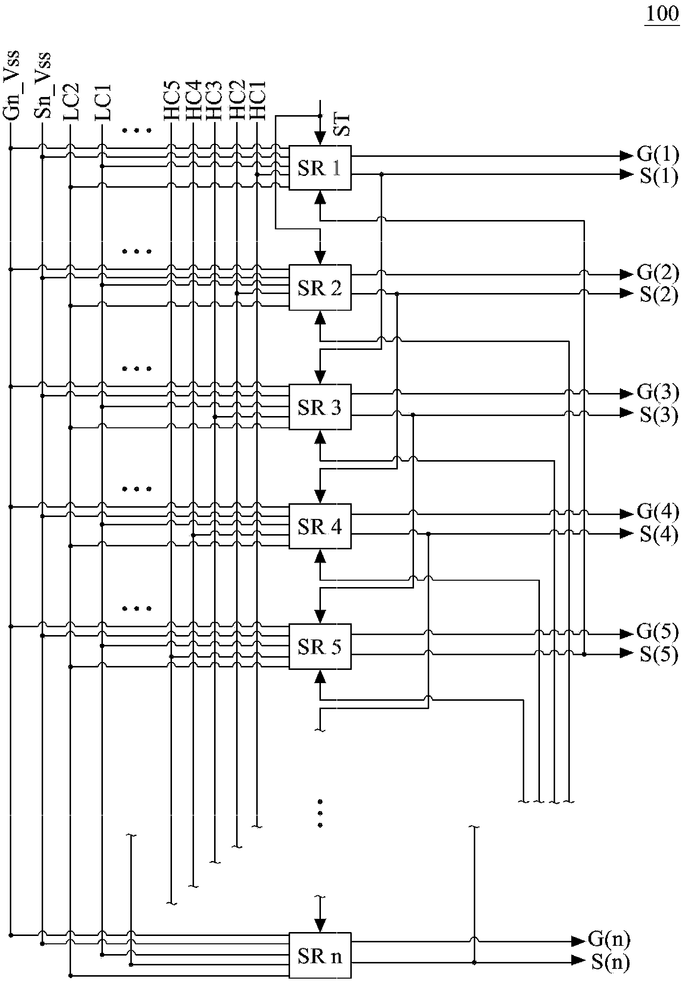
[0034] Please refer to figure 1 , which is a system block diagram of a shift register according to an embodiment of the present invention. The shift register includes multi-stage shift register circuits SR1~SRn connected in series, and the plurality of shift register circuits SR1~SRn receive a...


PUM


Abstract

A shifting register circuit comprises a pull-up control circuit used for providing a pull-up control signal, a first pull-up circuit used for providing a sensing drive signal according to the pull-up control signal and a second clock pulse signal, a second pull-up circuit used for providing a grid electrode drive signal according to a first clock pulse signal, the pull-up control signal, and the second clock pulse signal, a first pull-down control circuit used for outputting a first pull-down control signal, a first pull-down circuit used for pull down the pull-up control signal, the sensing drive signal, and the grid electrode drive signal according to the first pull-down control signal, and a main pull-down circuit used for pull down the grid electrode drive signal.

Description

【Technical field】 [0001] The invention relates to a shift register circuit, in particular to a shift register circuit applicable to a touch display device. 【Background technique】 [0002] Liquid crystal display devices have the advantages of being light, thin and small, and have gradually replaced traditional bulky cathode ray tube (CRT) displays, and are widely used in various types of electronic products. With the miniaturization of the size of electronic products, there is not enough space on the products to accommodate traditional input devices such as keyboards and mice. Therefore, touch display devices that combine touch input and display functions are currently widely used in various formula products. There are many types of touch display devices, which are mainly classified into resistive, capacitive, ultrasonic and infrared sensing according to their touch sensing principles. When the touch panel touches, the touch position is obtained according to the sensed capa...

Claims


Application Information

Patent Timeline
Patent Type & Authority Applications(China)
IPC IPC(8): G11C19/28G09G3/36
CPCG06F3/0412G11C19/28G06F3/041G06F2203/04103G09G2310/0286
Inventor 林炜力董哲维陈嘉亨侯淑方
Owner AU OPTRONICS CORP
Why Eureka
Try Eureka