Carbon brush component and carbon brush assembly with same

A carbon brush and component technology, applied in electrical components, current collectors, rotary current collectors, etc., can solve the problems of wasting human resources, reducing motor work efficiency, and unable to achieve continuous production.

Active Publication Date: 2013-11-20
JIANGSU HUAYU CARBON
View PDF3 Cites 2 Cited by
  • Summary
  • Abstract
  • Description
  • Claims
  • Application Information

AI Technical Summary

Problems solved by technology

[0003] Existing carbon brushes need to be replaced after long-term use, which not only reduces the working efficiency of the motor, but also wastes human resources and cannot achieve continuous production

Method used


Image

  • Carbon brush component and carbon brush assembly with same
  • Carbon brush component and carbon brush assembly with same
  • Carbon brush component and carbon brush assembly with same

Examples


Embodiment 2

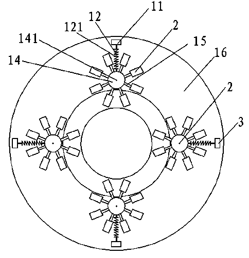
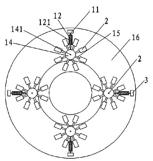
[0029] see image 3 and Figure 4 , the rest is the same as the first embodiment, the difference is that the first base 11 is also provided with a telescopic passage 121, and the elastic member 12 is disposed in the telescopic passage 121.

[0030] This ensures that the direction of the elastic force of the elastic member 12 is correct.

Embodiment 3

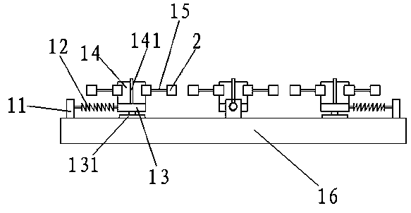
[0032] see Figure 5 and Figure 6 , as shown in the legend therein, the rest is the same as the first embodiment, the difference is that the rotating shaft 141 is also connected with the servo motor 17, the second base 13 is also connected with the servo cylinder 18, and the piston rod of the servo cylinder 18 It is connected to the second base 13 and the expansion and contraction direction is the same as that of the elastic member 12; the servo motor 17 and the servo cylinder 18 are electrically connected to an external controller.

[0033] When the carbon brush 2 is worn out, the external controller controls the servo cylinder 18 to make the second base 13 retreat along the sliding guide member 131, and at the same time controls the servo motor 17 to drive the rotating shaft 141 to rotate, so that the third base 14 rotates along the rotating shaft 141, so that The other carbon brushes 2 rotate to the position where they are in contact with the commutator, thereby achieving...

Embodiment 4

[0035] The rest is the same as that of Embodiment 3, except that a sensor is arranged on the fourth base, and the sensor senses the position of the connecting rod and transmits the signal to the external controller; the external controller controls the connection of the servo motor and servo cylinder.

[0036] When the sensor senses that the connecting rod reaches a certain position, it indicates that the carbon brush has almost worn out, and the sensor sends a control signal to the external controller, which can realize the automation of brush replacement.


PUM


Abstract

The invention discloses a carbon brush component. The carbon brush component comprises a carbon brush holder and a plurality of carbon brushes which are arranged on the carbon brush holder, wherein the carbon brush holder comprises a first base, an elastic piece, a second base, a third base and a plurality of connection rods; one end of the elastic piece is connected with the first base; the second base is connected to the other end of the elastic piece; the third base is rotatably connected to the second base through a rotary shaft; the connection rods are circumferentially arranged on the third base and are perpendicular to the rotary shaft; the carbon brushes are correspondingly connected to the connection rods. The carbon brush component disclosed by the invention is provided with the plurality of electric brushes which are circumferentially arranged along the rotation direction; when one of the electric brushes is worn away, another electric brush can quickly rotate to a place in contact with the surface of a commutator by rotation of the third base; the carbon brushes are always in contact with the outer surface of the commutator, so that electric energy can be continuously conveyed to coils through the commutator. The invention also discloses a carbon brush assembly with the carbon brush component.

Description

technical field [0001] The invention relates to a carbon brush assembly, in particular to a carbon brush assembly using the carbon brush assembly. Background technique [0002] A carbon brush is a device that transmits energy or signals between the fixed part and the rotating part of a motor or generator or other rotating machinery. When used in a brushed motor, the carbon brush is on the surface of the commutator. When the motor rotates, the electric energy is transferred It is sent to the coil through the commutator. Since the main component of the carbon brush is carbon, and it is easy to wear, it should be regularly maintained and replaced, and the carbon deposit should be cleaned. [0003] The existing carbon brush needs to be replaced after a long period of use, and the replacement not only reduces the working efficiency of the motor, but also wastes human resources and cannot realize continuous production. Contents of the invention [0004] In order to solve the ab...

Claims


Application Information

Patent Timeline
Patent Type & Authority Applications(China)
IPC IPC(8): H01R39/26H01R39/38
Inventor 周兵
Owner JIANGSU HUAYU CARBON
Why Eureka
Try Eureka