Horizontal flow precipitation separation device

A technology of sedimentation separation and horizontal flow, applied in the sedimentation tank and other directions, can solve the problems of complex structure of sedimentation separation device, easy to produce disturbance, easy to block the sludge discharge port, etc., to achieve fast and effective sedimentation effect, avoid disturbance effect, and ensure sedimentation speed Effect

Inactive Publication Date: 2013-11-27
ZHEJIANG DEAN TECH
View PDF1 Cites 10 Cited by
  • Summary
  • Abstract
  • Description
  • Claims
  • Application Information

AI Technical Summary

Problems solved by technology

[0004] The above-mentioned horizontal tube sedimentation and separation device partly improves the problem that the water flow and the direction of solid precipitation are easily disturbed, but the structure of the sedimentation and separation device is relatively complicated, and it also has high requirements for on-site installation, which limits its practicability; on the other hand, when the suspension When the types and sizes of the objects are relatively complicated, especially the large-sized suspended objects are easy to block the sludge outlet, and the sediment is easy to deposit on the inclined sludge discharge slide, blocking the sludge discharge channel; when the sedimentation is serious, it exceeds the bearing load of the horizontal pipe will cause the device to collapse

Method used


Image

  • Horizontal flow precipitation separation device
  • Horizontal flow precipitation separation device
  • Horizontal flow precipitation separation device

Examples


Embodiment 1

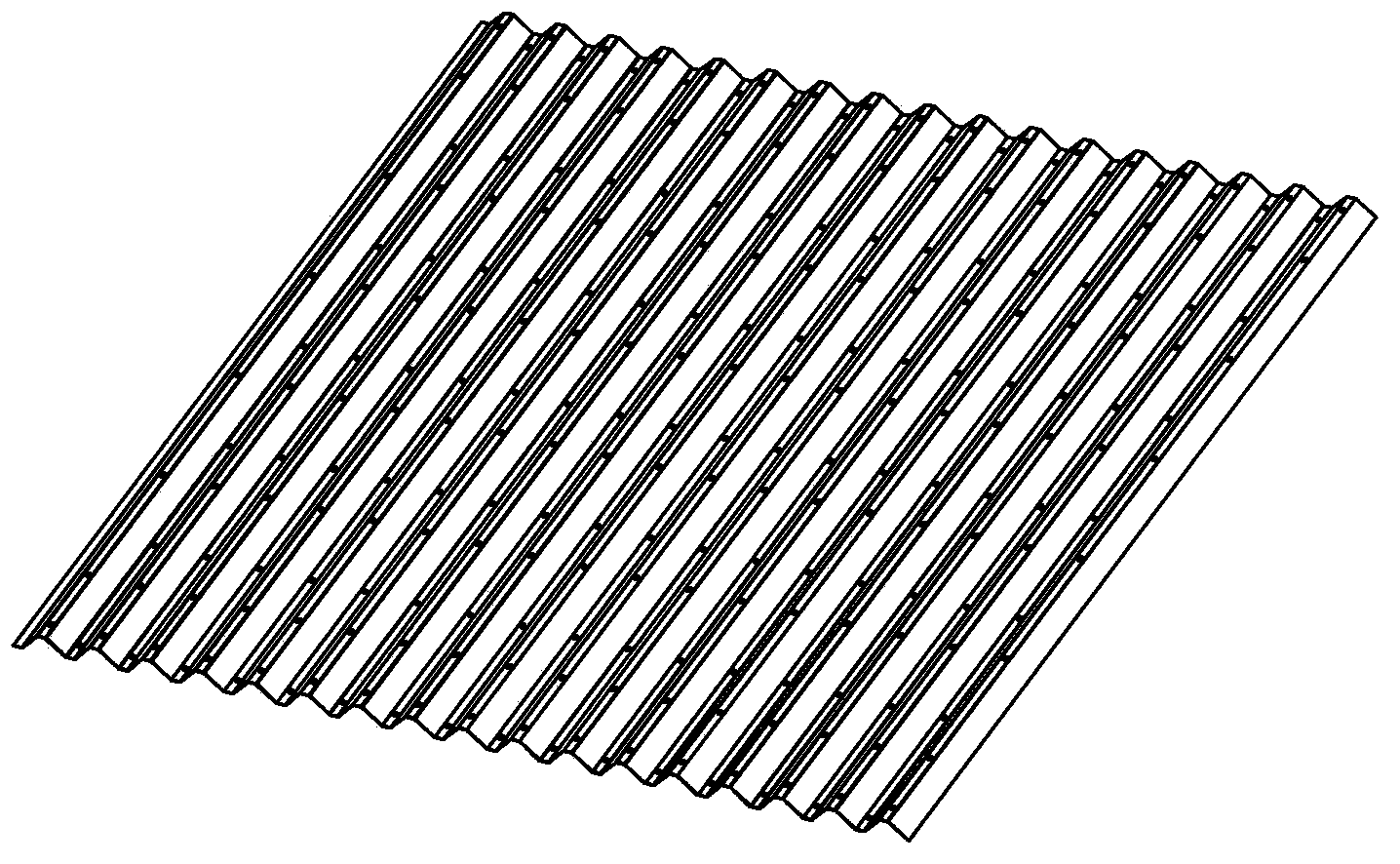
[0028] like Figure 1 to Figure 5 As shown, the horizontal flow sedimentation separation device is installed in the sedimentation tank 12, which includes:

[0029] There are multiple corrugated plates 1, and these corrugated plates are arranged vertically relative to the horizontal plane, and the cross-section of the corrugated plates has a trapezoidal wave structure. The trapezoidal wave in this embodiment is an isosceles trapezoid, and the included angle α between the two waists and the corresponding valley bottom is 45°, and the width of the valley bottom is 1 cm. The width of the valley bottom can also select other sizes according to needs, usually Between 0.5 and 2 cm. The length of the two waists is 3 centimeters; the length of the waist can also be selected for other sizes as required, such as 2 to 3.5 centimeters.

[0030] In this embodiment, the surface of each corrugated pipe has a hydrophobic layer, thereby effectively reducing the resistance of the surface of the...

Embodiment 2

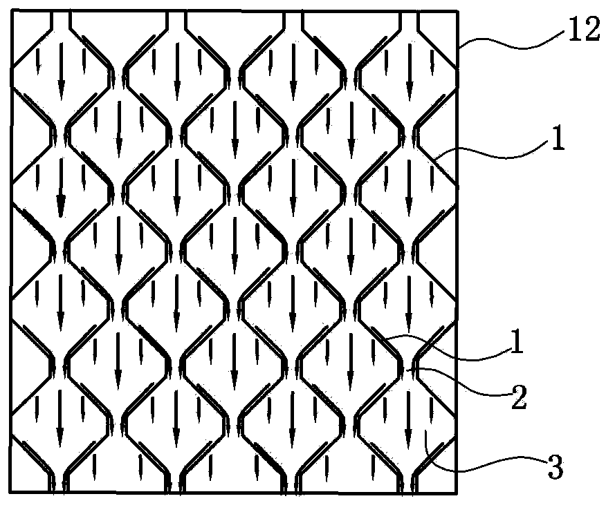
[0037] like Figure 6 to Figure 8 As shown, the horizontal flow sedimentation separation device includes:

[0038] There are multiple corrugated plates 1, and these corrugated plates are arranged vertically relative to the horizontal plane, and the cross-section of the corrugated plates has a trapezoidal wave structure. The trapezoidal wave in this embodiment is an isosceles trapezoid, and the included angle α between the two waists and the corresponding valley bottom is 45°, and the width of the valley bottom is 1 cm. The width of the valley bottom can also select other sizes according to needs, usually Between 0.5 and 2 cm. The length of the two waists is 3 centimeters; the length of the waist can also be selected for other sizes as required, such as 2 to 3.5 centimeters.

[0039] In this embodiment, the surface of each corrugated pipe has a hydrophobic layer, thereby effectively reducing the resistance of the surface of the corrugated plate to the sediment, and speeding u...


PUM

PropertyMeasurementUnit
widthaaaaaaaaaa

Abstract

The invention relates to a horizontal flow precipitation separation device. The horizontal flow precipitation separation device is characterized by comprising multiple corrugated plates arranged in a precipitation pond, wherein each corrugated plate is vertically arranged relative to a horizontal plane, the adjacent corrugated plates are symmetrically arranged and are spaced, and the smallest interval of the adjacent corrugated plates serves as a sludge discharging channel. Compared with the prior art, the horizontal flow precipitation separation device preserves the advantages that a flow direction and a precipitate sludge discharging direction are mutually vertical without interfering with each other, the disturbance between the horizontal flow and a precipitate is avoided, the submerged sludge is prevented from suspending again, meanwhile, a sludge discharging manner is optimized, the vertical sludge discharging channel is adopted, when stream horizontally flows through a stream channel, suspended solids are collided with a frame of the stream channel to rapidly precipitate, and slide downwards along the frame to enter the sludge discharging channel so as to directly precipitate to the bottom of the precipitation pond, and a wobble plate does not need to bear load, so that a problem of load-bearing of the wobble plate caused by large precipitate quantity is solved.

Description

technical field [0001] The invention relates to the technical field of water treatment, in particular to a horizontal flow sedimentation and separation device for solid and liquid separation with supporting sedimentation facilities. Background technique [0002] The sedimentation and separation device is the basic unit in water treatment technology, and the research and development of high-efficiency sedimentation device has always been the focus of attention of those skilled in the art. At present, the sedimentation and separation device with inclined tube or inclined plate structure widely used in the sedimentation tank can effectively increase the sedimentation area and improve the sedimentation effect, but the direction of water flow is parallel to the direction of sedimentation, and the liquid and solid are prone to interference, which affects the sedimentation effect. ; It is easy to accumulate mud, block the inclined pipe or inclined plate, and then deform the incline...

Claims


Application Information

Patent Timeline
Patent Type & Authority Applications(China)
IPC IPC(8): B01D21/02
Inventor 俞建德
Owner ZHEJIANG DEAN TECH
Why Eureka
Try Eureka