Four-foot bio-robot leg

A bionic robot, thigh technology, applied in the field of robot legs, can solve problems such as single movement structure

A bionic robot, thigh technology, applied in the field of robot legs, can solve problems such as single movement structure

CN103407514AInactive Publication Date: 2013-11-27NORTHWESTERN POLYTECHNICAL UNIV

Image

  • Four-foot bio-robot leg
  • Four-foot bio-robot leg
  • Four-foot bio-robot leg

Examples


Embodiment Construction

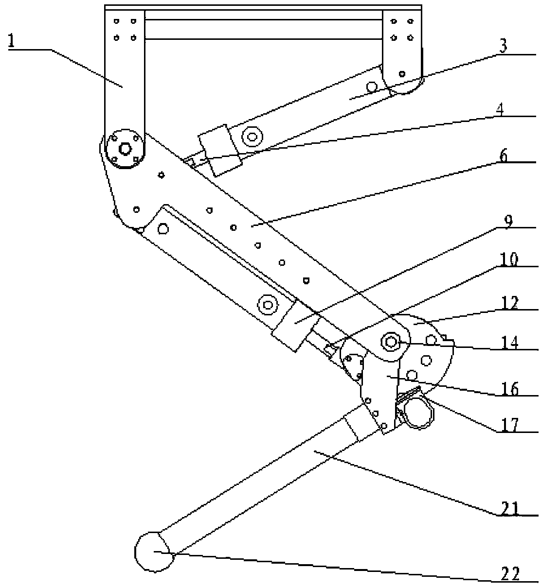
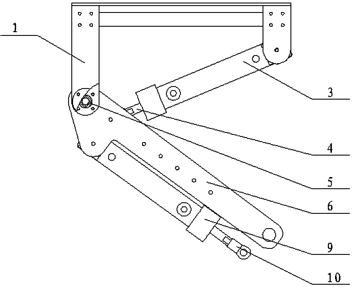
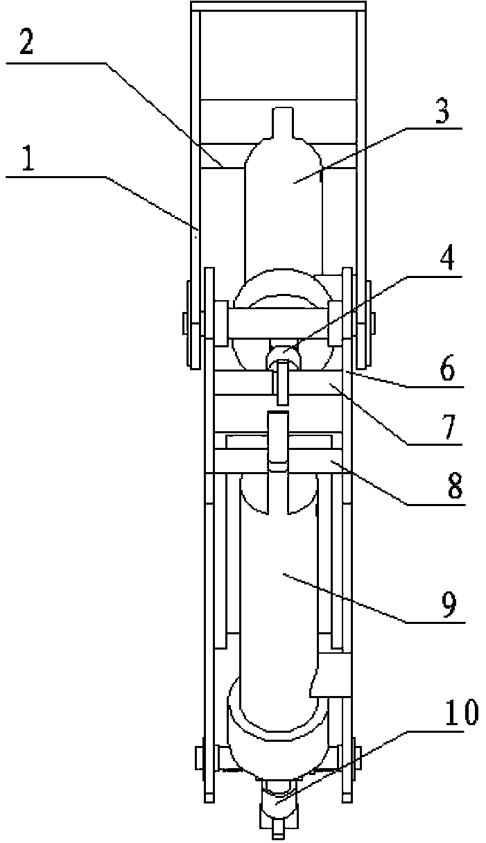
[0020] The following examples refer to Figure 1-8 .

[0021] This embodiment is a single leg of a hydraulically driven rigid-flexible compound quadruped robot. The robot leg is composed of a body, a thigh, a joint rigid-flexible modulation mechanism, and a lower leg. The power drive device adopts hydraulic drive. On the basis of the rigid structure, a flexible link spring is set to buffer and absorb shock. The body part is composed of a body support 1, a body hydraulic cylinder shaft 2, a first hydraulic cylinder body 3 and a first hydraulic cylinder piston rod 4. Body is connected with thigh connecting bearing 5 with thigh. The thigh part is made up of the thigh support 6, the first hydraulic cylinder shaft 7 of the thigh, the second hydraulic cylinder shaft 8 of the thigh, the cylinder block 9 of the second hydraulic cylinder and the piston rod 10 of the second hydraulic cylinder. The joint stiffness-flexibility modulation mechanism is composed of the joint disc 12 and ...


PUM


Abstract

The invention discloses a four-foot bio-robot leg which is used for solving the technical problem of a single movement structure, caused by a rigid structure, of an existing robot leg. According to the technical scheme, the four-foot bio-robot leg is composed of an articular disc, an articular disc hydraulic cylinder shaft rigid and soft regulating mechanism, rigid structures such as a machine body support, a thigh support, a crus connecting rod, a crus connecting plate, an articular disc limiting block, a crus supporting base, a crus sleeve and soft structures such as a sole. A power drive device is driven in a hydraulic mode. Due to the fact that a soft link spring is arranged based on the rigid structure to buffer and absorb vibration, and the cooperation of the articular disc and the articular disc limiting block imitates the human body knee-joint tissue, the crus can move flexibly, go upstairs, jump and do other movements.

Description

technical field [0001] The invention relates to a robot leg, in particular to a quadruped bionic robot leg. Background technique [0002] With its discrete support movement, footed robots show strong adaptability and flexibility in complex terrain and unpredictable environments. It has broad application prospects in construction and other fields. High speed and high mobility are one of the development trends of legged robots, and the robot legs, as an important motion support system of legged robots, directly determine the kinematics and dynamics characteristics of the robot, and play an important role in the high speed and high mobility of legged robots. influences. Taking the common quadruped mammal "dog" biological leg as the bionic prototype, based on its biological "skeleton-muscle" anatomical characteristics and "skeleton-muscle" integrated motion characteristics, the design of the bionic quadruped robot leg for running is a footed robot another development trend. ...

Claims


Application Information

Patent Timeline
27 Nov 2013
Publication
CN103407514A
IPC
B62D57/032
Inventors
张雪峰; 李芳昕