Flow homogenizing plate used for crystalline silicon diffusion and crystalline silicon diffusion technology furnace comprising same

A technology of diffusion process and uniform flow plate, which is applied in the directions of crystal growth, diffusion/doping, after treatment, etc., to achieve the effect of improving air flow uniformity, improving uniformity, reducing replacement cost and maintenance time

Inactive Publication Date: 2013-11-27
TIANWEI NEW ENERGY HLDG
View PDF12 Cites 1 Cited by
  • Summary
  • Abstract
  • Description
  • Claims
  • Application Information

AI Technical Summary

Problems solved by technology

[0010] The purpose of the present invention is to provide a uniform flow plate for crystalline silicon diffusion and a crystalline silicon diffusion process furnace. The square resistance uniformity problem caused by the gas flow direction in the tail area has played a very good role in improving the uniformity of the diffusion square resistance, P 2 o 5 It will not cause damage to the uniform flow plate, and there are no multiple maintenance and safety problems

Method used


Image

  • Flow homogenizing plate used for crystalline silicon diffusion and crystalline silicon diffusion technology furnace comprising same
  • Flow homogenizing plate used for crystalline silicon diffusion and crystalline silicon diffusion technology furnace comprising same
  • Flow homogenizing plate used for crystalline silicon diffusion and crystalline silicon diffusion technology furnace comprising same

Examples


Embodiment 1

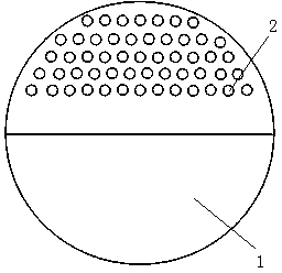
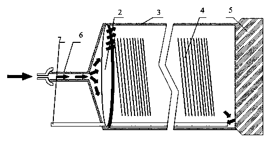
[0031] Such as figure 1 with image 3 shown.

[0032] The uniform flow plate used for the diffusion of crystalline silicon is characterized in that it includes a uniform flow plate body 1, and the uniform flow plate body 1 is divided into a furnace top plate area and a furnace bottom plate area according to the area, and a number of uniform flow holes 2 are opened in the furnace top plate area. The furnace floor area is a sealed plate body.

[0033] The realization principle is: use the uniform flow plate instead of the uniform flow pipe, and set the uniform flow hole 2 for diversion on the uniform flow plate body 1, and the uniform flow hole 2 is only located in the furnace roof area, that is, the uniform flow plate body 1 is installed into the process furnace After inside the body 3, the uniform flow hole 2 is located in the upper area of ​​the furnace body 3 of the process furnace, which can cause the process gas to rise after passing through the uniform flow hole 2, so t...

Embodiment 2

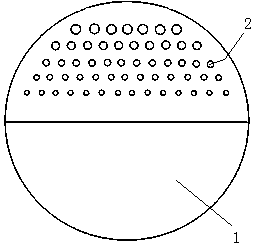
[0045] Such as figure 2 shown.

[0046] The difference between this embodiment and Embodiment 1 is that the size of the uniform flow holes 2 changes from large to small from the furnace roof area to the furnace floor area, and the uniform flow holes 2 of the same height are uniformly distributed in the furnace roof area.

[0047] In the above embodiments, the size of the uniform flow hole 2 is not uniform, and the closer to the top of the furnace body 3 of the process furnace, the larger the hole is. It is preferred to change in a ratio of 10%, that is, the size ratio between the adjacent uniform flow holes 2 in the direction from the top of the process furnace body 3 to the bottom of the process furnace body 3 is 10%.

Embodiment 3

[0049] This embodiment is based on Embodiment 1 and Embodiment 2: the hole axis of the uniform flow hole 2 and the axis of the process furnace body 3 form an included angle of 30°-80°. The uniform flow hole 2 rises and points to the top of the furnace body 3 of the process furnace. This can further cause the airflow to rise. Preferably, the data between 80 degrees and 60 degrees or between 80 degrees and 60 degrees is used for experiments.

[0050] The arrows in the figure indicate the flow direction of the process gas.

[0051] Data description: such as Figure 4 with Figure 5 as shown, Figure 4 Among them, there are 500 pieces of polysilicon 4 inside the furnace body of the process furnace, and among the 500 pieces of polysilicon 4, 5 pieces are selected at equal intervals to measure the square resistance data, such as image 3 As shown, the five pieces of polysilicon 4 used for measuring square resistance data are respectively: piece 1A, piece 2B, piece 3C, piece 4D,...


PUM


Abstract

The invention discloses a flow homogenizing plate used for crystalline silicon diffusion and a crystalline silicon diffusion technology furnace comprising the same. The flow homogenizing plate comprises a flow homogenizing plate body, wherein the flow homogenizing plate body is divided into a furnace top plate region and a furnace bottom plate region according to regions; a plurality of flow homogenizing through holes are formed in the furnace top plate region; and the furnace bottom plate region is a sealed plate body. The flow homogenizing plate has the beneficial effects that 1. the change cost and the maintenance time are reduced while the homogeneity of the airflow in the furnace body is improved, thus achieving the cost reducing and benefit increasing effects; 2. risks caused by corrosion fracture of a flow homogenizing pipe, such as square resistance abnormity and the like, are reduced; and 3. the flow homogenizing plate further plays a role in homogenizing gases, and improves the homogeneity of square resistance after diffusion.

Description

technical field [0001] The invention relates to a crystalline silicon diffusion device, in particular to a uniform flow plate for crystalline silicon diffusion and a crystalline silicon diffusion process furnace. Background technique [0002] In the production process of crystalline silicon solar cells, POCL3 liquid source diffusion is commonly used to make PN junctions. The principle is to place crystalline silicon in a furnace body and pass in process gas for diffusion. During the diffusion process, the process gas enters the furnace from the end of the furnace tube through a cup, and the tail gas and unreacted gas are drawn out from the furnace mouth through the tail gas pipe. [0003] Using this method for diffusion has simple process and low cost, so it has become the main method for producing PN junctions in crystalline silicon solar cells at present. [0004] Since the temperature of the process gas entering from the furnace tail is low (room temperature), the proces...

Claims


Application Information

Patent Timeline
Patent Type & Authority Applications(China)
IPC IPC(8): C30B31/16C30B31/10
Inventor 程曦匡成国姜涛杨东姚骞包崇彬
Owner TIANWEI NEW ENERGY HLDG
Why Eureka
Try Eureka