
Excitation valve

A technology of excitation valve and spool, applied in the field of hydraulic control, can solve the problems of complex control system, insufficient flow rate, high output frequency of excitation valve, etc.

Inactive Publication Date: 2013-11-27
江海兵
View PDF6 Cites 5 Cited by
  • Summary
  • Abstract
  • Description
  • Claims
  • Application Information

AI Technical Summary

Problems solved by technology

However, due to the use of servo motors, its control system is still relatively complicated, and the output frequency of the excitation valve is high, but the flow rate is not large enough. Therefore, based on the principle of the servo screw mechanism disclosed in my country's invention application 96113491.7, significant improvements have been made and developed. A large-flow excitation valve with simple control to meet engineering needs

Method used


Image

  • Excitation valve
  • Excitation valve
  • Excitation valve

Examples


Embodiment 1

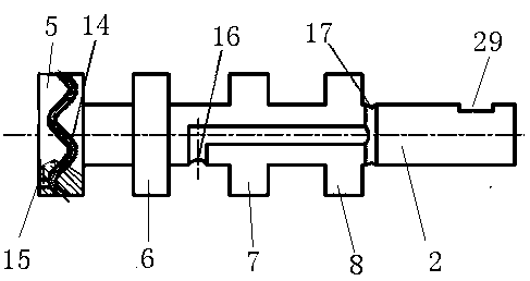
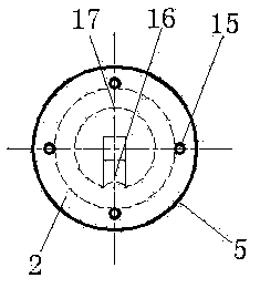
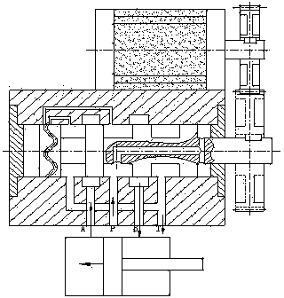
[0016] Embodiment 1: An excitation valve is composed of a valve body 1, a valve core 2, a left end cover 3, and a right end cover 4. The excitation valve is essentially a three-position four-way electrically driven reversing valve. The three bits are left, middle, and right. The four-way is the control port A25, the main oil inlet port 20, the control port B27, and the oil return port T23. The valve core 2 is provided with a throttling shoulder 5, a control shoulder A6, and a control shoulder B7 from left to right. , The high-pressure shoulder 8 protrudes from the opening on the right end cover 4, and the protruding end is provided with a keyway 29. Through the keyway 29, the torque is connected by the motor and the gear set, so that the spool 2 rotates, and then the axial reciprocating motion of the spool 2 is generated, and the oil inlet reversing of the control port A25 and the control port B27 is realized; the corresponding excitation valve The valve chamber is divided in...

Embodiment 2

[0017] Embodiment 2: A vibration-exciting valve, in which a wave-shaped groove 14 is provided on the peripheral surface of the throttling shoulder 5, specifically a sine wave with a wave number of 4, the groove is 2 mm deep, and 3 mm to ensure that the valve core 2 is in the neutral position When the opening is 0.11. The other structures of the valve are the same as in Embodiment 1, and the spool of the vibration valve is equipped with a flange and directly connected with a frequency conversion stepper motor. If the rotation frequency of the motor is set to 100Hz, then the output frequency of the excitation valve is 4×100=400 Hz.

Embodiment 3

[0018] Embodiment 3: A vibration-exciting valve, in which a wave-shaped groove 14 is formed on the peripheral surface of the throttling shoulder 5, specifically a sine wave with a wave number of 6, with a groove width of 3 mm and a groove depth of 3 mm to ensure that the valve core 2 is in the neutral position When the opening is 0.2. The working principle of the excitation valve is the same as that of the first two embodiments, except that the valve body and the valve core are manufactured by 3D printing technology. If the rotation frequency of the motor is set to 50Hz, the output frequency of the excitation valve is 6×50=300 Hz, because the groove width of the waveform groove is larger than that of the previous two embodiments, and the openings of the high-pressure hole and the low-pressure hole are also the same. Larger, the output flow of the excitation valve also becomes larger, that is, the output power becomes larger.

[0019] In a word, the present invention is diffe...


PUM

PropertyMeasurementUnit
Groove widthaaaaaaaaaa

Abstract

The invention relates to a valve, particularly relates to an excitation valve, and belongs to the field of hydraulic control in the fluid power transmission and control field. The technical scheme includes that the excitation valve comprises a valve body, a valve element, a left end cover and a right end cover, and is essentially a three-position four-way electrically-driven reversing valve, the three-position four-way electrically-driven reversing valve has a left position, a middle position and a right position and is provided with a control port A, a main oil inlet, a control port B and an oil return port T, a throttle shoulder, a control shoulder A, a control shoulder B and a high-pressure shoulder which are respectively provided with wavy grooves are sequentially arranged on the valve element from left to right, the valve element extends out of an opening in the right end cover, and a key slot is formed in the extending end of the valve element. Torque is connected into the excitation valve via the key slot, so that the valve element can rotate and further can axially reciprocate, and oil inlet directions of the control port A and the control port B can be changed. Compared with the traditional pilot-operated electromagnetic valve or 2D (two-dimensional) high-frequency excitation valve, the excitation valve has the advantages of simplicity in control, high flow, applicability to specific vibration test benches and wide range of engineering application places.

Description

technical field [0001] The invention relates to a valve, in particular to an excitation valve, which belongs to the field of hydraulic control in the field of fluid transmission and control. Background technique [0002] Vibration test is a basic test in the field of modern engineering technology. It is widely used in many important engineering fields, such as environmental experiments of missiles and rockets; road simulation experiments of automobiles and walking machinery; engineering material tests; earthquake resistance of dams and high-rise buildings test etc. Most of the vibrating tables used are electro-hydraulic, because they have the advantages of stepless amplitude modulation, frequency modulation, large output force, simplified system and easy realization of automatic control. The 2D high-frequency excitation valve developed by Zhejiang University of Technology is the core of the current electro-hydraulic vibration table. The valve has two degrees of freedom, tha...

Claims


Application Information

Patent Timeline
IPC IPC(8): F16K11/085F16K11/07
Inventor 江海兵陆青洪郑圣宏张鹏
Owner 江海兵
Learn More