Eureka AIR delivers breakthrough ideas for toughest innovation challenges, trusted by R&D personnel around the world.

Damping sleeve for metal pipe vibration and noise reduction and coating method

A vibration and noise reduction, metal pipe technology, applied in the direction of pipes/pipe joints/fittings, pipe elements, springs, etc., can solve problems such as complex construction, reduced vibration and noise reduction effects, complex production processes, etc., to achieve construction quality and Improve construction efficiency, ensure vibration reduction effect, and ensure the effect of coverage area

Inactive Publication Date: 2013-11-27
725TH RES INST OF CHINA SHIPBUILDING INDAL CORP
View PDF7 Cites 3 Cited by
  • Summary
  • Abstract
  • Description
  • Claims
  • Application Information

AI Technical Summary

Problems solved by technology

[0004] All hydraulic system pipelines, hovering system pipelines and seawater cooling system pipelines on domestic ships adopt the damping coating method, that is, the outer surface of the pipelines is coated with damping tape. The damping tape is produced by 3M Company of the United States. The constraining layer of the tape is aluminum foil and the thickness of the aluminum foil layer is 0.2-0.25mm and the thickness of the damping layer is 0.125mm. This method of wrapping the damping tape is relatively complicated during construction, and it is subject to certain restrictions on the construction of ships. many
[0005] The document "Test Method for Vibration Reduction Performance of Pipeline Damping Materials" uses damping tape to dampen and coat metal pipelines. The production process is complex, construction is difficult, and construction quality is difficult to guarantee, thereby reducing the effect of vibration reduction and noise reduction.

Method used


Image

  • Damping sleeve for metal pipe vibration and noise reduction and coating method
  • Damping sleeve for metal pipe vibration and noise reduction and coating method

Examples

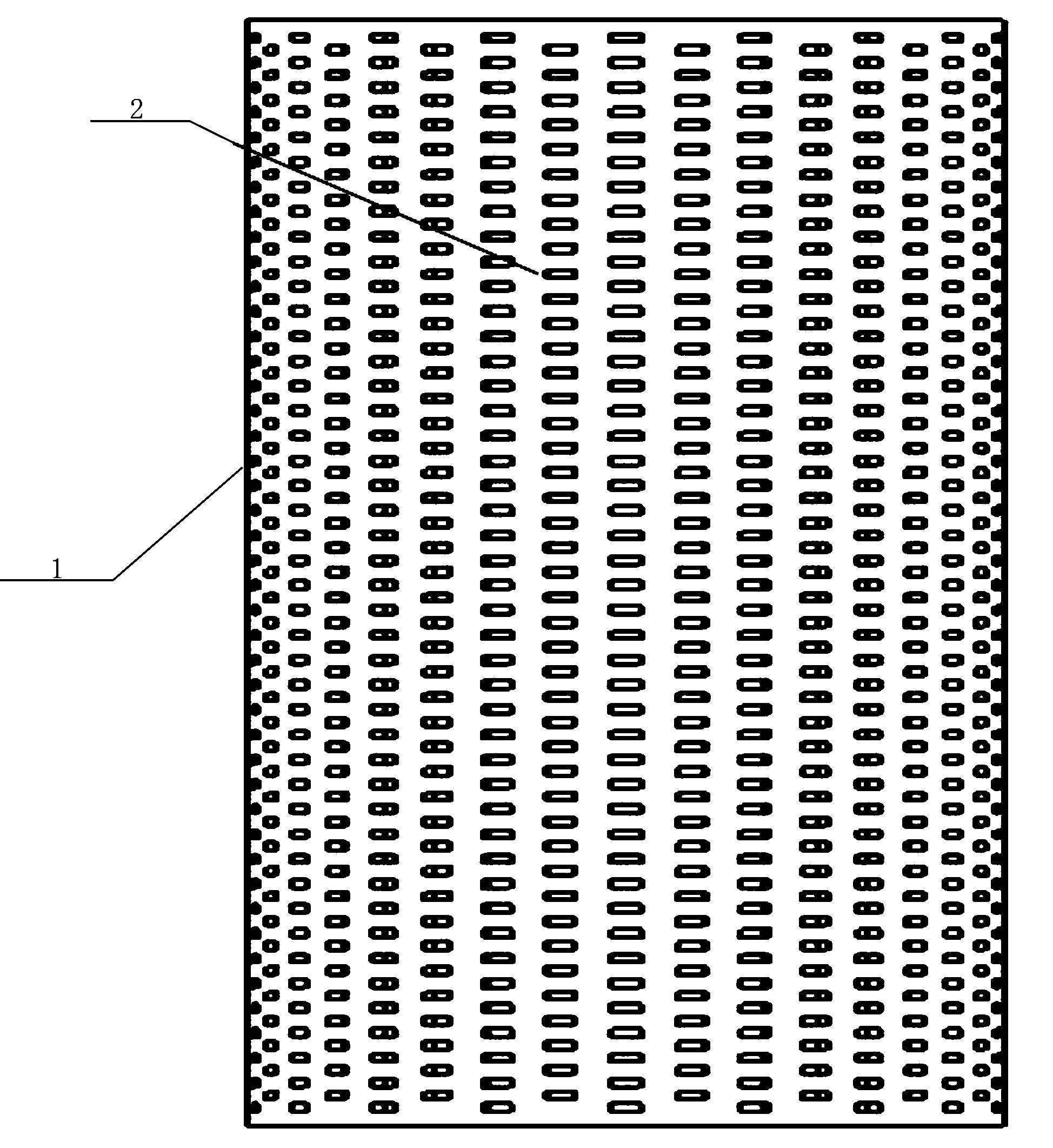
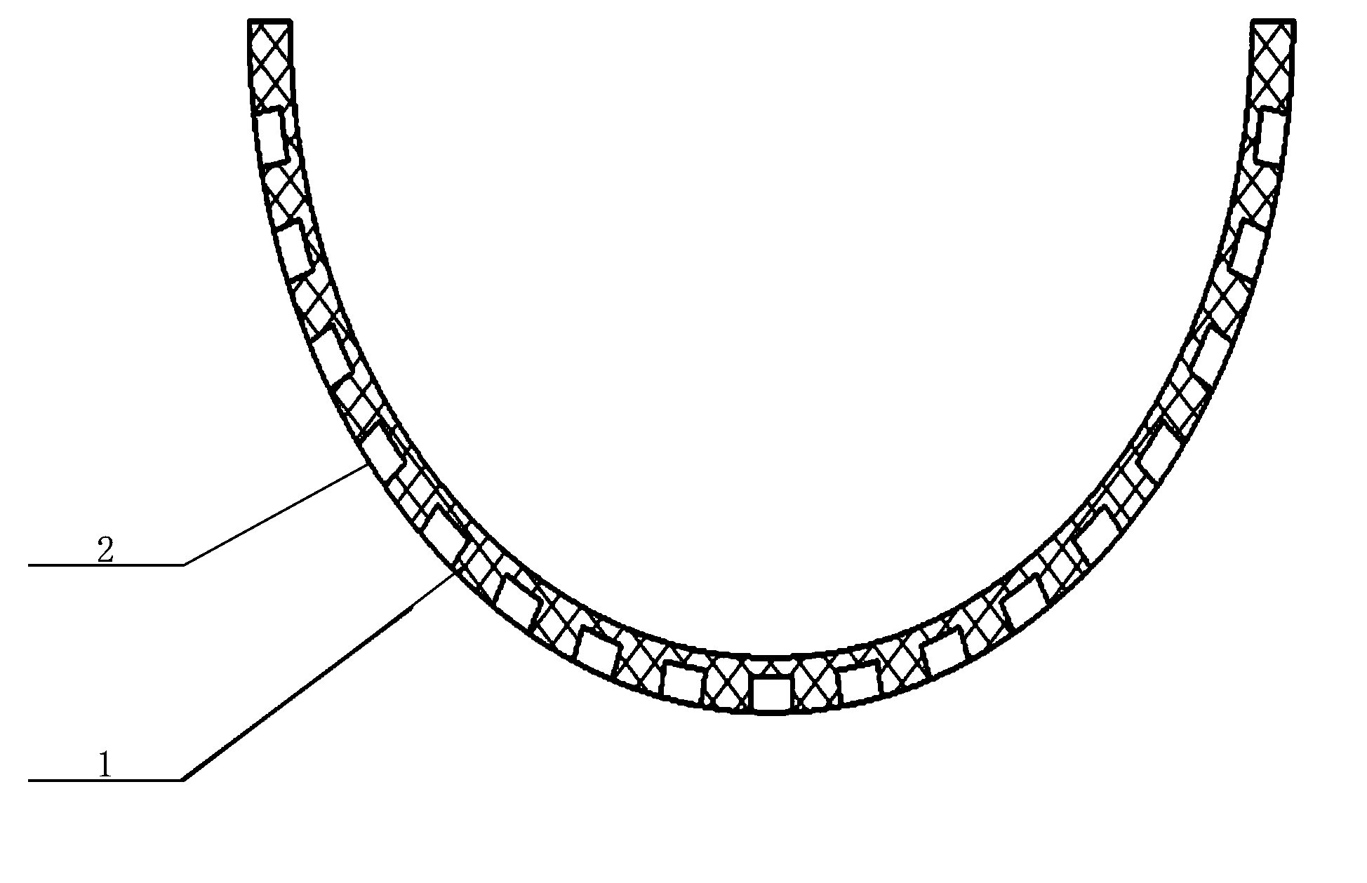

Embodiment Construction

[0025] The invention relates to a damping sleeve used for vibration and noise reduction of metal pipelines and a cladding method.

[0026] The outer diameter of the metal pipeline is set as D, and the diameter of D can reach Φ30-Φ300mm.

[0027] combine Figure 1-2 , the damping sleeve 1 with a thickness of T is mostly semi-cylindrical and made of rubber material. The material is either neoprene, nitrile rubber, or polyurethane rubber, and an anti-aging agent is added to the rubber material.

[0028] The inner diameter of the multi-semi-cylindrical shape matches D, the expanded width of the multi-semi-cylindrical shape is ≥3лD / 4, and several cavity holes 2 are arranged on the outer surface of the damping sleeve, and several cavity holes 2 are arranged along the damping sleeve The axial direction of the pipe 1 is arranged in several rows, the distance between two adjacent cavity holes in each row is equal to K, and the distance between the cavity holes in adjacent rows is als...


PUM


Abstract

The invention discloses a damping sleeve for metal pipe vibration and noise reduction and a coating method. The damping sleeve (1) with the thickness of T is in a more-than-one-half cylinder shape and made of rubber materials. A plurality of cavity holes (2) are formed in the outer surface of the damping sleeve (1). Redundant parts of the two damping sleeves (1) are cut off in the 45-degree direction of the axis to enable the two damping sleeves (1) to define a whole circle and form a pairing damping sleeve. The inner wall of the paring damping sleeve and the outer wall of a metal pipe are evenly painted with glue, the pairing damping sleeve coats the outer wall of the metal pipe, joint closing is carried out on the pairing damping sleeve in the 45-degree included angle direction, then the pairing damping sleeve is wound and tightly tied up through woven belts, and the woven belts are removed after the glue is completely solidified. The thick pairing damping sleeve coats the metal pipe, the impedance sudden change is formed between the metal pipe and the pairing damping sleeve, therefore, vibration energy can be absorbed through the cavity holes in the pairing damping sleeve when vibration is generated on the metal pipe, and the vibration noise of the metal pipe is reduced.

Description

technical field [0001] The invention belongs to the technical field of metal pipeline vibration reduction and noise reduction, in particular to a damping sleeve and a coating method for metal pipeline vibration reduction and noise reduction. Background technique [0002] Metal pipelines play the role of transmitter in equipment vibration, and have the function of "acoustic bridge" for vibration and noise transmission. Therefore, the vibration and noise reduction of metal pipelines has always been the focus of research. Noise measures include: damping cladding of metal pipelines or the use of flexible pipes and other measures. [0003] The damping coating of metal pipelines is one of the most commonly used methods of vibration reduction and noise reduction. Damping coating can effectively attenuate the vibration amplitude of metal pipelines, reduce the transmission direction of vibration along metal pipelines, and also reduce the transmission direction of vibration to metal p...

Claims


Application Information

Patent Timeline
Patent Type & Authority Applications(China)
IPC IPC(8): F16L55/033F16F1/377
Inventor 林新志赵树磊马玉亮
Owner 725TH RES INST OF CHINA SHIPBUILDING INDAL CORP
Why Eureka
Eureka Blog
Learn More