Rate gyroscope calibrating method

A technology of rate gyroscope and calibration method, which is applied in the direction of measuring devices and instruments, and can solve the problems such as the complexity of the rate gyroscope error calibration process

Inactive Publication Date: 2013-11-27
NORTHWESTERN POLYTECHNICAL UNIV
View PDF8 Cites 11 Cited by
  • Summary
  • Abstract
  • Description
  • Claims
  • Application Information

AI Technical Summary

Problems solved by technology

[0003] In order to overcome the shortcomings of the existing rate gyro error calibration process complex, the present invention provides a rate gyro calibration method

Method used


Image

  • Rate gyroscope calibrating method
  • Rate gyroscope calibrating method
  • Rate gyroscope calibrating method

Examples


Embodiment Construction

[0024] The specific steps of the rate gyro calibration method of the present invention are as follows:

[0025] Under the room temperature condition, the experiment carried out on the 3SK-150 type non-magnetic turntable by the miniature heading and attitude measurement system of three-axis MEMS accelerometer, three-axis MEMS angular rate gyroscope and three-axis miniature fluxgate sensor is carried out as an example to the present invention illustrate. The method steps are as follows:

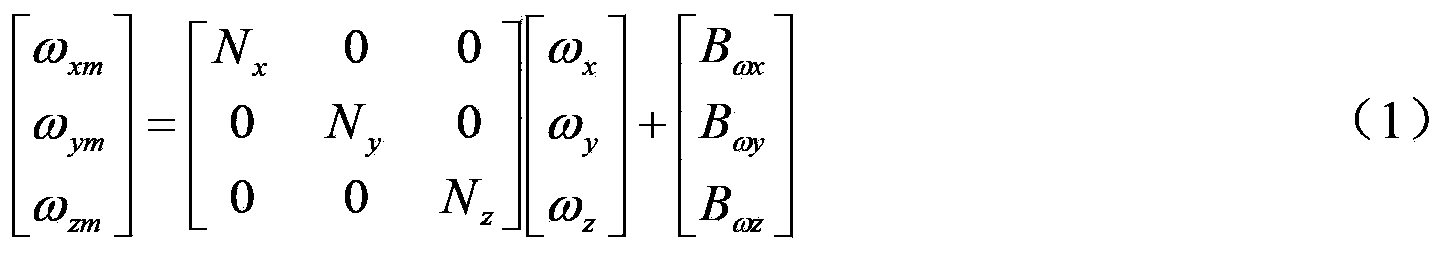
[0026] (1) Establish the error model of the rate gyroscope as follows:

[0027] ω xm ω ym ω zm = N x ...


PUM


Abstract

The invention discloses a rate gyroscope calibrating method which is used for solving the technical problem of complicated error calibration process of an existing rate gyroscope. According to the technical scheme, a carrier respectively rotates around an X axis, a Y axis and a Z axis and a rotation angle rate of the carrier is calculated according to output data change of a magnetic sensor so as to be used as a reference angle rate of calibrating a rate gyroscope, and a scale factor and a zero offset error of each axis of the rate gyroscope are respectively calibrated. According to the rate gyroscope calibrating method, a rate rotary table is not needed, realizing conditions are simple and online rapid calibration is facilitated. Through testing, the static precision of the gyroscope can drift within 2.5 DEG for 10min, and when an input angle rate is less than 25 DEG/s under a dynamic condition, errors of three axes can be kept to be within +/-2 DEG.

Description

technical field [0001] The invention relates to a gyroscope calibration method, in particular to a rate gyroscope calibration method. Background technique [0002] The calibration of the rate gyroscope is mainly done by using the position calibration method or the rate calibration method on the rate turntable. The document "Calibration and Compensation Method of Micro-Small Strapdown Inertial Measurement Unit, Li Jianli, Fang Jiancheng, Sheng Wei, etc., Acta Astronautics Sinica, 2008, 03:947-951" discloses a calibration and compensation method of micro-miniature strapdown inertial measurement unit. According to the mathematical model of the angular velocity and acceleration channel error of the micro-miniature inertial measurement unit, the method designs the "six-direction positive and negative rate" test, and uses the three-axis rate turntable to set the X, Y, and Z axes of the miniature strapdown inertial measurement unit and the earth coordinate system respectively. The...

Claims


Application Information

Patent Timeline
Patent Type & Authority Applications(China)
IPC IPC(8): G01C25/00
Inventor 刘诗斌陈露兰张韦
Owner NORTHWESTERN POLYTECHNICAL UNIV
Why Eureka
Try Eureka