
Liquid crystal display and driving method of gate signal thereof

A liquid crystal display and gate driver technology, applied in static indicators, instruments, etc., can solve the problems of grid wiring waveform distortion, impedance rise, panel rewriting, etc., and achieve the effect of improving the fall time

Active Publication Date: 2015-11-25
NANJING CEC PANDA LCD TECH
View PDF7 Cites 0 Cited by
  • Summary
  • Abstract
  • Description
  • Claims
  • Application Information

AI Technical Summary

Problems solved by technology

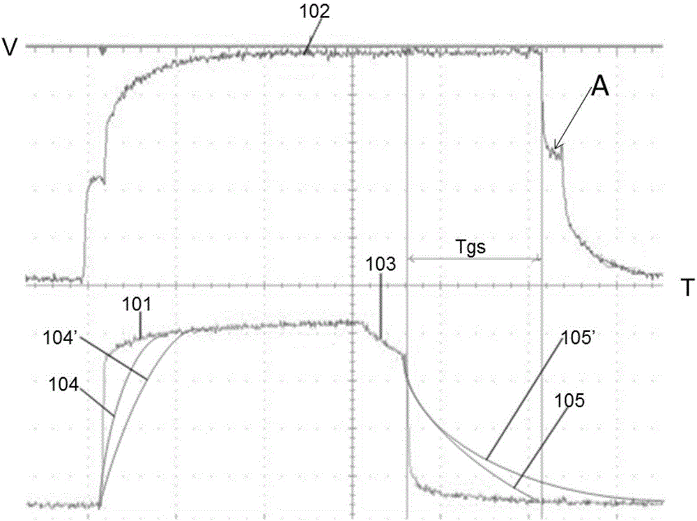
[0009] Purpose of the invention: While not changing the charging capacity of the TFT in the prior art and not reducing the aperture ratio of the liquid crystal panel, in order to improve the resistance of the grid wiring when the temperature of the liquid crystal panel rises, the impedance of the gate wiring will increase with the increase of temperature, and the change will be made. As a result, the waveform distortion at the farthest point of the gate wiring is more serious, and when the phase difference between the waveforms of the gate and the source driver is insufficient, rewriting may occur on the panel after the temperature rises

Method used


Image

  • Liquid crystal display and driving method of gate signal thereof
  • Liquid crystal display and driving method of gate signal thereof
  • Liquid crystal display and driving method of gate signal thereof

Examples


Embodiment Construction

[0031] Below in conjunction with accompanying drawing and specific embodiment, further illustrate the present invention, should be understood that these embodiments are only for illustrating the present invention and are not intended to limit the scope of the present invention, after having read the present invention, those skilled in the art will understand various aspects of the present invention Modifications in equivalent forms all fall within the scope defined by the appended claims of this application.

[0032] The present invention proposes a driving method of a liquid crystal display and its grid signal. The driving method of the grid signal of the present invention effectively improves the resistance of the grid wiring when the temperature of the liquid crystal panel rises. If the increase is higher, the waveform distortion at the farthest end of the gate wiring will be more serious, which will easily cause the problem of rewriting the LCD panel.

[0033] refer to F...


PUM


Abstract

The invention discloses a liquid crystal displayer which comprises a power supply circuit for supplying grid electrode starting voltage signals and a grid electrode driver. The liquid crystal displayer further comprises a corner cut circuit respectively connected with the power supply circuit and the grid electrode driver. The corner cut circuit comprises a corner cut control logic circuit, wherein when corner cut control signals obtained after logical operation of received corner cut voltage signals are changed from a high level to a low level by the corner cut control logic circuit, the grid electrode starting voltage signals begin to discharge and have corner cut waveforms, and the discharging duration of the grid electrode starting voltage signals and slopes of the corner cut waveforms change along with temperature of operation environment of the displayer. The corner cut circuit which can be properly adjusted along with changes of the temperature is additionally arranged, and accordingly signal reduction time caused by grid wiring after the temperature of the operation environment of the liquid crystal displayer rises is reduced, and the problem that wrong optical phenomena of pixels occur after the temperature of the operation environment of the liquid crystal displayer rises can be solved.

Description

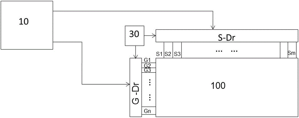
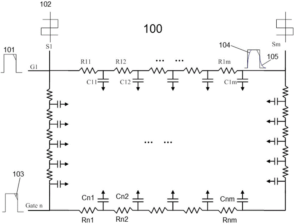
technical field [0001] The invention relates to a liquid crystal display and a driving method for a gate signal thereof, in particular to a liquid crystal display gate driving circuit and a driving method thereof. Background technique [0002] Liquid crystal displays have been widely used in fields such as monitors, notebook computers, and televisions because of their low radiation, light and thin volume, and low power consumption. [0003] Such as figure 1 Shown is a schematic diagram of a prior art liquid crystal display, the display includes a matrix liquid crystal panel 100, the panel is arranged with m source signal lines S1 to Sm in the vertical direction, and n gate signal lines G1 are arranged in the horizontal direction To Gn, a plurality of pixel units are separated and bounded by a plurality of the gate signal lines and the source signal lines and are distributed in a matrix (not shown in the figure). In each pixel unit, a pixel electrode and a A signal switch T...

Claims


Application Information

Patent Timeline
Patent Type & Authority Patents(China)
IPC IPC(8): G09G3/36
Inventor 廖木山卢建宏蓝东鑫
Owner NANJING CEC PANDA LCD TECH
Learn More