
CMOS ring oscillator based on silicon-on-insulator process

A technology of ring oscillator and silicon-on-insulator, which is applied in the direction of semiconductor devices, electric solid-state devices, electrical components, etc., can solve the problems of circuit failure risk, affecting circuit performance, reliability reduction, etc., and achieves improved rising edge time and simple circuit structure, the effect of improving the fall time

Inactive Publication Date: 2011-06-29
EAST CHINA NORMAL UNIV
View PDF0 Cites 0 Cited by
  • Summary
  • Abstract
  • Description
  • Claims
  • Application Information

AI Technical Summary

Problems solved by technology

[0004] At present, the main process technologies used in the design of ring oscillators in the field of integrated circuits include traditional bulk silicon RFCMOS technology and SiGe BiCMOS technology, of which SiGe BiCMOS technology is generally used in the design of LC voltage-controlled oscillators to provide better phase noise performance; traditional bulk silicon RFCMOS technology is more suitable for the design of ring oscillators. However, the limitations of traditional bulk silicon RFCMOS technology in terms of noise and characteristic frequency make it not dominant in high-frequency, high-performance RF applications
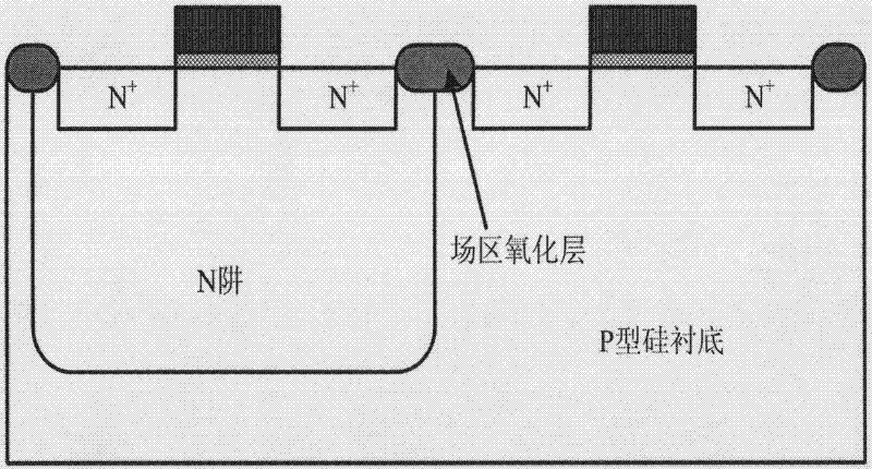
[0005] Cross-sectional view of traditional bulk silicon CMOS device structure, such as figure 2 As shown, the active area of ​​the device is directly on the substrate, and full dielectric isolation cannot be achieved. The resulting parasitic thyristor latch-up effect will cause potential failure of the circuit. At the same time, due to the shrinking feature size, the power supply voltage The soft failure problem caused by the reduction will reduce the anti-interference ability of the circuit and reduce the reliability
[0006] The chip area occupied by the isolation region between traditional bulk silicon CMOS devices will increase as the device size decreases, resulting in more parasitic capacitance, which is not conducive to improving integration density and circuit speed
At the same time, various multi-dimensional nonlinear effects will become more obvious due to the shrinking of the device size, which will seriously affect the circuit performance.

Method used


Image

  • CMOS ring oscillator based on silicon-on-insulator process
  • CMOS ring oscillator based on silicon-on-insulator process
  • CMOS ring oscillator based on silicon-on-insulator process

Examples


Embodiment Construction

[0027] The technical solution of the present invention is a specific embodiment, and will not be repeated here. Describe the working process of the present invention in detail below.

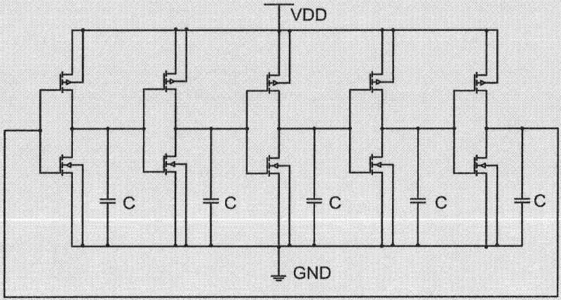
[0028] refer to Figure 4 , when the IN terminal is high level, after the power supply voltage starts to supply power, the first MOS transistor M1 and the second

[0029] The inverter formed by the MOS transistor M2 outputs a low level, that is, the phase inversion is completed through the first stage (stage 1); at the same time, the inverter formed by the third MOS transistor M3 and the fourth MOS transistor M4 outputs a high level, that is, The inversion is completed through the second stage (stage2); the inverter formed by the fifth MOS transistor M5 and the sixth MOS transistor M6 outputs a low level, that is, the inversion is completed through the third stage (stage3); the seventh MOS transistor M7 and the The inverter composed of the eighth MOS transistor M8 outputs a high level, that is, ...


PUM


Abstract

The invention discloses a CMOS ring oscillator based on a silicon-on-insulator process. In the technical scheme, a circuit design adopts connection of a depletion type silicon-floating-body-on-insulator (FB) NMOS tube with the source end of an enhanced silicon-on-insulator body connected with a (BC) NMOS tube, and the structure with a special device suspended in the tube body area of the floatingbody improves the relationship between rise time and a power voltage and the relevance of frequency output and the power voltage, thereby better providing stable frequency output. Due to the high-resistance substrate and the buried oxidation layer of the silicon-on-insulator process device, the invention significantly reduces the crosstalk, minimizes the parasitic capacitance and better shields the substrate noise. Moreover, the invention has the advantages of small changes in oscillation frequency along with changes in the power supply, simple circuit and high practicality.

Description

technical field [0001] The invention relates to the technical field of integrated circuit design and signal processing, in particular to a complementary metal oxide semiconductor (CMOS) ring oscillator based on silicon-on-insulator technology. Background technique [0002] With the rapid development of wireless communication technology, high-performance, low-cost phase-locked loop (Phase Lock Loop) circuits and their basic unit oscillators are increasingly required in the field of radio frequency front-end applications. The phase-locked loop is an important component of the phase-locked loop module circuit in communication circuits and high-speed systems. It is mainly used to generate time references, and its performance determines the performance of the entire system. The Voltage-Controlled Oscillator (Voltage-Controlled Oscillator) is the unit that works at the highest frequency in the phase-locked loop circuit. In recent years, people have conducted extensive research on ...

Claims


Application Information

Patent Timeline
Patent Type & Authority Patents(China)
IPC IPC(8): H01L27/12
Inventor 石春琦陈磊赖宗声
Owner EAST CHINA NORMAL UNIV
Learn More