Ring main unit self-powered system

A technology of power supply system and ring network cabinet, which is applied in the direction of current collectors, electric vehicles, electrical components, etc. It can solve the problems of losing the main source of power supply, the failure of the battery to supply power normally, and the performance impact of the battery discharge capacity, etc., and achieves simple structure and easy implementation , low-cost effect

Inactive Publication Date: 2013-11-27
STATE GRID CORP OF CHINA +2
View PDF6 Cites 4 Cited by
  • Summary
  • Abstract
  • Description
  • Claims
  • Application Information

AI Technical Summary

Problems solved by technology

The power can be obtained by arranging DC battery packs, but the site of the ring network cabinet is greatly affected by the external environment temperature, especially the discharge capacity of the battery at high and low temperatures and the performance after long-term deep discharge will be greatly affected. Can not supply power normally, and will lose the main source of power once the line is powered off at the site

Method used


Image

  • Ring main unit self-powered system

Examples


Embodiment Construction

[0014] The present invention will be further described below in conjunction with accompanying drawing.

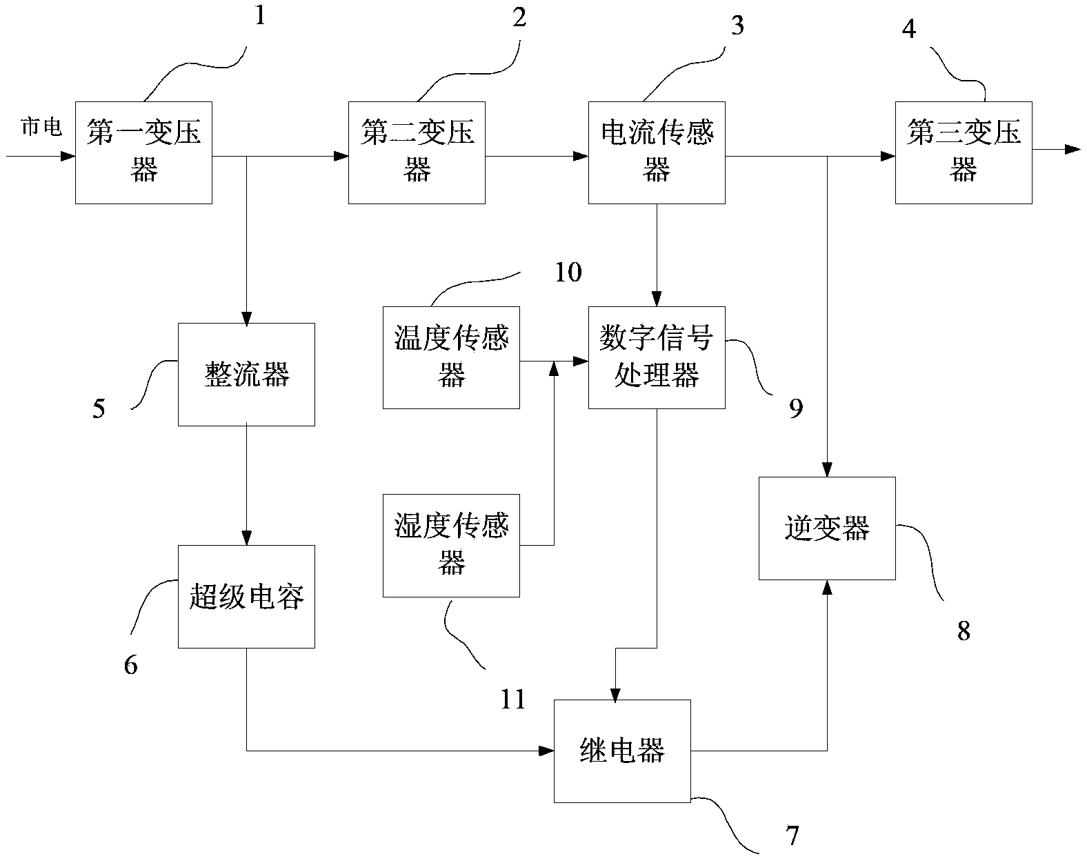
[0015] see figure 1 , the ring main unit self-power supply system of the present invention includes a first transformer 1, a second transformer 2, a current sensor 3, a third transformer 4, a rectifier 5, a supercapacitor 6, a relay 7, an inverter 8, and a digital signal processor 9. Temperature sensor 10 and humidity sensor 11, wherein:

[0016] The first transformer 1, the second transformer 2, the current sensor 3 and the third transformer 4 are sequentially connected; the input end of the first transformer 1 is connected to the mains, and the output end is connected to the input end of the second transformer 2;

[0017] The rectifier 5, the supercapacitor 6, the relay 7 and the inverter 8 are sequentially connected; the input end of the rectifier 5 is connected to the output end 1 of the first transformer; the output end of the inverter 8 is connected to the input end ...


PUM


Abstract

The invention discloses a ring main unit self-powered system which comprises a first transformer, a second transformer, a current sensor and a third transformer, wherein the first transformer, the second transformer, the current sensor and the third transformer are sequentially connected. The ring main unit self-powered system further comprises a rectifier, a super capacitor, a relay, an inverter, a digital signal processor, a temperature sensor and a humidity sensor, wherein the rectifier, the super capacitor, the relay and the inverter are sequentially connected. An input end of the first transformer is connected with the alternating current; an input end of the rectifier is connected with an output end of the first transformer; an output end of the inverter is connected with an input end of the third transformer; the digital signal processor is respectively connected with the current sensor, the relay, the temperature sensor and the humidity sensor. The ring main unit self-powered system is low in cost and capable of guaranteeing continuous electricity supply to a ring main unit under various conditions, especially in the high-temperature environment and in the low-temperature environment.

Description

technical field [0001] The invention relates to a self-power supply system of a ring network cabinet. Background technique [0002] As an extremely important part of the power distribution system, the ring network cabinet is extremely important for its safe and reliable operation. Therefore, it is particularly important to ensure its uninterrupted power supply in various harsh working environments. The power can be obtained by arranging DC battery packs, but the site of the ring network cabinet is greatly affected by the external environment temperature, especially the discharge capacity of the battery at high and low temperatures and the performance after long-term deep discharge will be greatly affected. Can not supply power normally, and will lose the main source of power once the line is powered off at the scene. Therefore, designing and realizing a reasonable and low-cost ring main unit self-power supply system is a problem that the applicant is committed to solving. ...

Claims


Application Information

Patent Timeline
Patent Type & Authority Applications(China)
IPC IPC(8): H02J11/00H02J9/06H02J7/02
Inventor 李烽王剑黄安林姚建歆许楫史华康金琪解蕾刘晨怡
Owner STATE GRID CORP OF CHINA
Why Eureka
Try Eureka