
Automatic capacity checking device and capacity checking method for direct-current power supply system of transformer substation

A technology for power supply systems and substations, applied in battery circuit devices, circuit devices, electric vehicles, etc., can solve problems such as the inability to ensure the stability of the DC bus voltage, the impact of normal operation of load equipment, and large personnel investment, so as to ensure uninterrupted power supply, Achieve energy reuse and realize the effect of remote operation

Pending Publication Date: 2021-10-15
WENZHOU ELECTRIC POWER BUREAU +2
View PDF11 Cites 3 Cited by
  • Summary
  • Abstract
  • Description
  • Claims
  • Application Information

AI Technical Summary

Problems solved by technology

[0006] When the existing technology is used for off-line nuclear capacity, manpower is required to participate in the system’s nuclear capacity work, which requires a lot of personnel investment; in order to speed up the nuclear capacity, external equipment such as resistance boxes must be used to consume the discharge energy. Although the discharge current increases, the energy is wasted. Many; if online nuclear capacity is adopted, since the load power of the substation’s daily use equipment is small, the maximum discharge current will not exceed the load current, so the discharge current is small and the discharge time is long, and the stability of the DC bus voltage during the nuclear capacity process cannot be guaranteed. Thus affecting the normal operation of the load equipment

Method used


Image

  • Automatic capacity checking device and capacity checking method for direct-current power supply system of transformer substation
  • Automatic capacity checking device and capacity checking method for direct-current power supply system of transformer substation

Examples


Embodiment Construction

[0022] The present invention will be further described below in conjunction with the accompanying drawings and specific embodiments, so that those skilled in the art can better understand the present invention and implement it, but the examples given are not intended to limit the present invention.

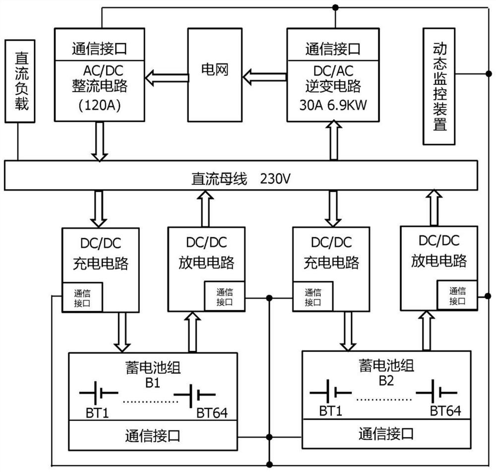
[0023] Such as figure 1 As shown, an automatic nuclear capacity device for a substation DC power supply system includes a DC bus, an AC / DC rectifier circuit, a DC / AC inverter circuit, and a battery pack. The input end of the AC / DC rectifier circuit is connected to the power grid, and the output end is connected to the DC The busbar is connected to the DC load, the input end of the DC / AC inverter circuit is connected to the DC busbar, and the output end is connected to the power grid. The regular load of the DC busbar is about 15A. The substation signal equipment, power-off protection, automatic device, The DC uninterruptible power supply equipment such as emergency lighting, emerg...


PUM


Abstract

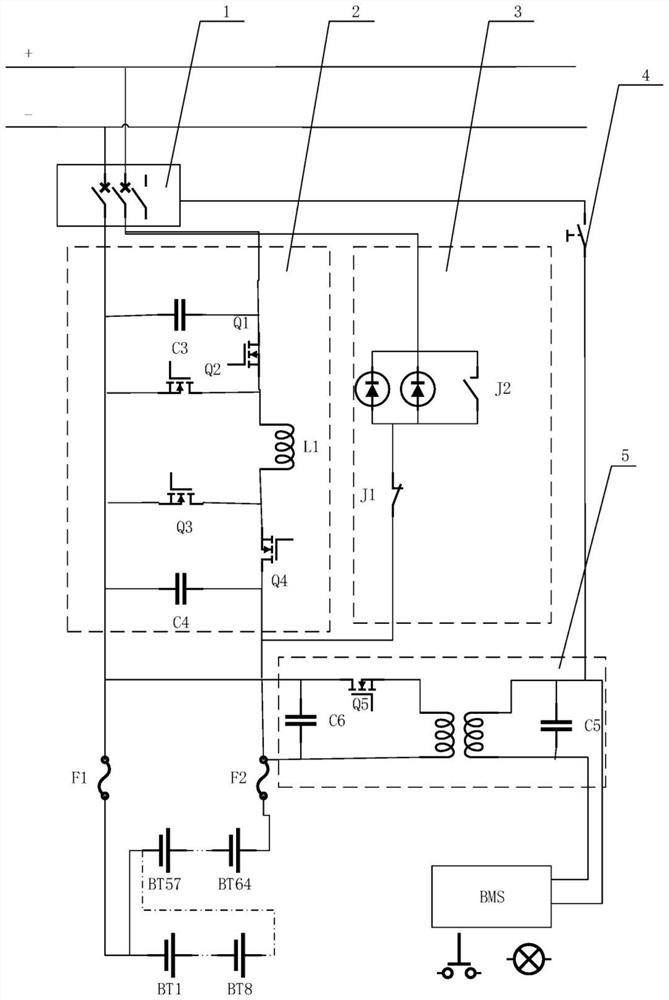
The invention relates to an automatic capacity checking device and a capacity checking method for a direct-current power supply system of a transformer substation, and the device consists of a storage battery pack AC / DC rectifying circuit, a DC / AC inverter circuit, a capacity checking circuit, a bidirectional buck-boost circuit, a battery management system, a communication interface and a dynamic monitoring circuit, the AC / DC rectifying circuit and the multi-path backup storage battery pack supply power to the direct current bus; and when capacity checking of discharging and charging of a storage battery pack is needed, an online capacity checking method is adopted, the discharging voltage and the charging voltage are adjusted through a bidirectional buck-boost circuit in the capacity checking circuit, a power grid is discharged through a DC / AC inverter circuit while a direct-current load is discharged, the discharging speed is increased, the AC / DC rectifying circuit is used for carrying out constant-current charging on the storage battery pack, stability of direct-current bus voltage is guaranteed in the discharging and charging process, automatic detection and remote monitoring of the charging and discharging state of the battery are achieved, human intervention is reduced, and recycling of discharging electric energy is achieved.

Description

technical field [0001] The invention relates to the field of direct current power supply of substations, in particular to a nuclear capacity device and a nuclear capacity method of a direct current power supply system of a substation. Background technique [0002] Substation DC power supply system widely serves hydraulic power, substations, thermal power plants and other users who use DC equipment. Power supply equipment. The DC power supply system is an independent power supply. It is not affected by the generator, plant power consumption and system operation mode. It can continue to provide DC power from the battery as a backup power supply when the external AC power is interrupted. [0003] The newly installed valve-regulated battery needs to be checked and discharged at full capacity during acceptance, and the full-capacity checked charge and discharge should be carried out every 6 months thereafter. After two years of operation, the valve-regulated battery should be ch...

Claims


Application Information

Patent Timeline
Patent Type & Authority Applications(China)
IPC IPC(8): H02J13/00H02J3/38H02J7/34H02J9/06
CPCH02J13/00016H02J3/38H02J7/34H02J9/061Y04S10/12Y04S10/50Y04S20/12Y04S40/128Y02E40/70Y02B90/20Y02E60/00Y04S10/16Y04S40/124
Inventor 王楠周喜超李振李娜胡春雨李矗易永利戴哲仁杨超余
Owner WENZHOU ELECTRIC POWER BUREAU
Learn More