Power switch device pulse transformer isolation driving circuit

A technology of power switching device and isolation drive circuit, which is applied to output power conversion devices, electrical components, and conversion equipment that can be converted to DC without intermediate conversion, and can solve the problem that the pulse transformer isolation drive circuit is not suitable for duty cycle changes. , can not reach the power switching device drive voltage amplitude, the negative amplitude is large, etc.

Inactive Publication Date: 2013-11-27
YANSHAN UNIV
View PDF9 Cites 27 Cited by
  • Summary
  • Abstract
  • Description
  • Claims
  • Application Information

AI Technical Summary

Problems solved by technology

It can be seen that after the pulse transformer Tr, the power switching device Q 1 The positive and negative amplitudes of the drive signal obtained are related to the duty cycle D of the PWM signal. When the duty cycle D is small, the positive amplitude of the drive signal is large, and the negative amplitude is small. When the value is large, the positive amplitude of the driving signal is small, and the negative amplitude is large, even failing to reach the Q of the power switching device. 1 required drive voltage amplitude, therefore, figure 1 The first pulse transformer isolated drive circuit shown is not suitable for applications with widely varying duty cycles

Method used


Image

  • Power switch device pulse transformer isolation driving circuit
  • Power switch device pulse transformer isolation driving circuit
  • Power switch device pulse transformer isolation driving circuit

Examples


Embodiment Construction

[0039] Below in conjunction with accompanying drawing and specific embodiment the present invention is described in further detail:

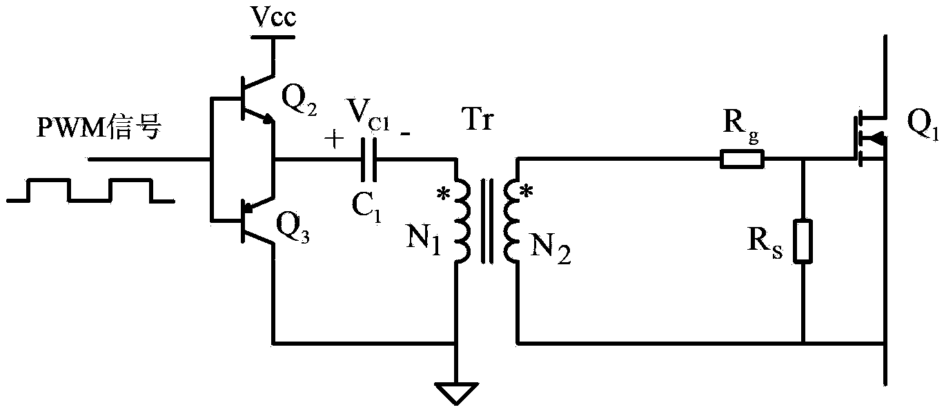
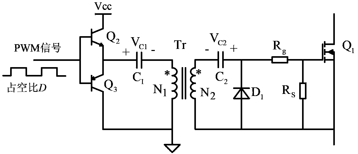
[0040] A power switching device pulse transformer isolation drive circuit, such as Figure 5 shown, it consists of an NPN transistor Q 2 , PNP transistor Q 3 , DC blocking capacitor C 1 , pulse transformer Tr, power switching device Q 1 , drive resistance R g , Gate discharge resistor R s , Diode D 1 and compensation capacitor C 2 , NPN transistor Q 2 and PNP transistor Q 3 Constitute a totem pole amplifier circuit, NPN transistor Q 2 The collector of the NPN transistor Q is connected to the positive pole of the power supply 2 The emitter of the PNP transistor Q 3 The emitter is connected, and connected to one end of the DC blocking capacitor, the PNP transistor Q 3 The collector of the circuit is connected to the reference ground of the circuit, and the NPN transistor Q 2 base of the PNP transistor Q 3 The bases are connected toge...


PUM


Abstract

The invention discloses a power switch device pulse transformer isolation driving circuit. The power switch device pulse transformer isolation driving circuit comprises a primary-side circuit, a pulse transformer Tr and a secondary-side circuit, wherein the primary-side circuit comprises an NPN transistor Q2, a PNP transistor Q3 and a blocking capacitor C1, and the secondary-side circuit comprises a power switch device Q1, a driving resistor Rg, a gate discharge resistor Rs, a diode D1, a compensation capacitor C2, a voltage-regulator tube Z1 and a negative pressure holding capacitor C3. The power switch device pulse transformer isolation driving circuit of the invention can be applied to all switching converters such as a boost converter, a buck converter, a forward converter, a flyback converter, a half-bridge switching converter, a half-bridge converter, a full-bridge converter and a push-pull converter, and can effectively improve the reliability of the switching converters.

Description

technical field [0001] The invention relates to the field of switch mode power converters, in particular to a pulse transformer isolation drive circuit for a power switching device in the power converter. Background technique [0002] In switch-mode power converters, power switching devices often need to be isolated and driven. The conventional method is to use optocoupler isolation plus a power amplifier circuit to drive the power switching devices, but this method requires an independent isolated driving power supply, which will increase additional costs. and circuit complexity. In small and medium power applications, pulse transformers are usually used to isolate the drive circuit to reduce additional drive power and reduce costs, such as figure 1 As shown, it is the first pulse transformer isolation driving circuit, which includes transistor Q 2 and Q 3 , DC blocking capacitor C 1 , pulse transformer Tr, Q 1 is the power switching device MOSFET (or IGBT) in the conv...

Claims


Application Information

Patent Timeline
Patent Type & Authority Applications(China)
IPC IPC(8): H02M5/10H02M1/44
Inventor 杨秋霞赵清林王德玉于志涛
Owner YANSHAN UNIV
Why Eureka
Try Eureka