
Video signal same frequency interference rejection device of electro-optical stabilized sight product

A technology for photoelectric stabilization and video signal, applied in transmission noise suppression, electrical components, transmission system, etc., can solve the problem of difficult to achieve high-definition display and electromagnetic compatibility requirements of products, and the filtering method cannot completely solve video signal co-channel interference, The complex electrical network and other problems can avoid screen flicker, the suppression effect is remarkable, and the video screen is clear.

Active Publication Date: 2013-11-27
西安应用光学研究所
View PDF3 Cites 0 Cited by
  • Summary
  • Abstract
  • Description
  • Claims
  • Application Information

AI Technical Summary

Problems solved by technology

The video transmission paths of the three CCDs are the same, and they are all connected to the same video processing circuit at the next level through video cables, and the three CCDs share a power supply network inside the turret, and the interference signal generated by one of the CCDs can easily pass through Video transmission lines and shared power lines are coupled to video signals output by other CCDs, resulting in co-channel interference
Since photoelectric stabilized aiming products have high-definition video display requirements, and the electrical network is complex, the filtering method cannot completely solve the problem of co-channel interference of video signals, and it is difficult to meet the high-definition display and electromagnetic compatibility requirements of the product.

Method used


Image

  • Video signal same frequency interference rejection device of electro-optical stabilized sight product
  • Video signal same frequency interference rejection device of electro-optical stabilized sight product
  • Video signal same frequency interference rejection device of electro-optical stabilized sight product

Examples


Embodiment Construction

[0017] The present invention will be further described in detail below in conjunction with the accompanying drawings and preferred embodiments.

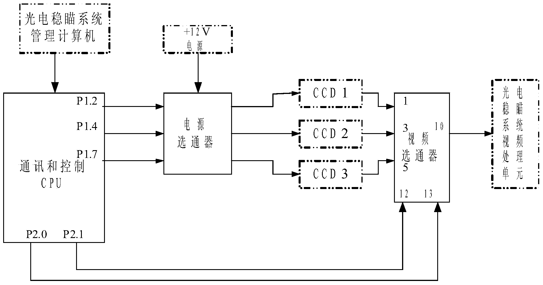
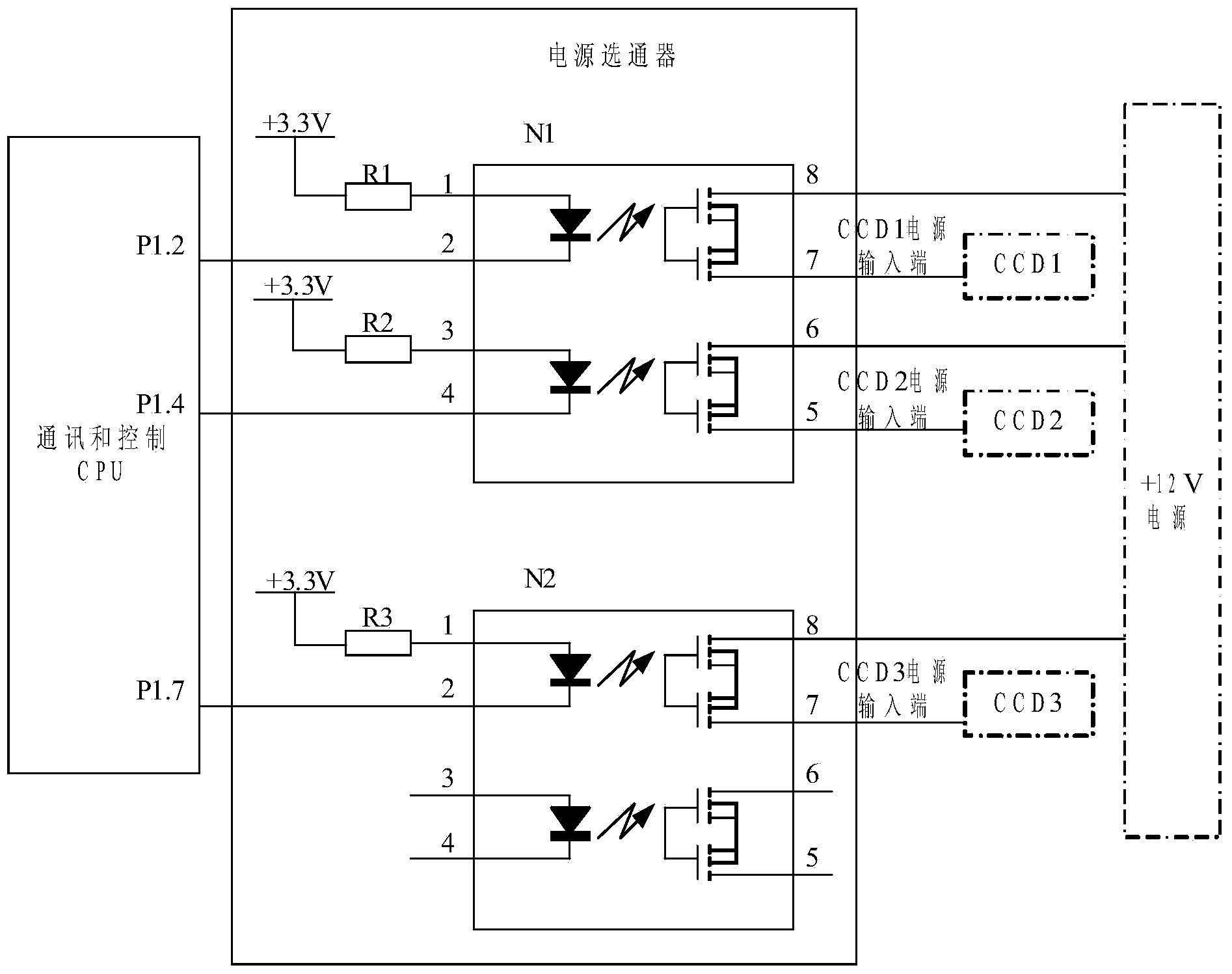
[0018] Such as figure 1 As shown, the preferred embodiment of the video signal co-channel interference suppression device of the present invention includes a CPU equipped with a control software package, a power gate and a video gate. In this embodiment, the CPU adopts a C8051 single-chip microcomputer; the video selector adopts a four-select-one multi-channel selector, and its model is AD8184.

[0019] The first input port of the video selector is that pin 1 is connected with the video output end of CCD1, the second input port is that pin 3 is connected with the video output end of CCD2, and the third input port is that pin 5 is connected with the video output end of CCD3. The output port, that is, 10 pins, is connected to the video processing unit of the photoelectric stabilization system. The strobe port of video strobe is conne...


PUM


Abstract

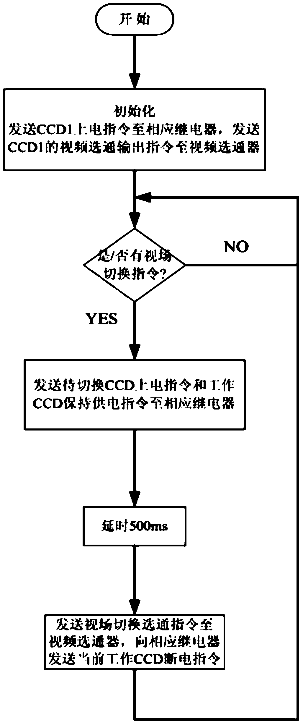
The invention discloses a video signal same frequency interference rejection device of an electro-optical stabilized sight product, and belongs to the technical field of electromagnetic compatibility. The device comprises a CPU, a power source gating device and a video gating device. A data port of the CPU is connected with the power source gating device and the video gating device. The power source input ends of three CCDs are connected with the power source gating device, and the output ends of the three CCDs are connected with the video gating device. When the CPU receives a view field switching order, the CCD to be switched is powered on through the power source gating device, when delayed time is up, the video gating device is controlled to gate the output of the CCD to be switched, and the CCD which works at present is controlled to be powered off. The same frequency interference problem of the three CCDs is radically solved, the electromagnetic compatibility of an electro-optical stabilized sight system is improved, and meanwhile the video signal same frequency interference rejection device has the advantages of being clear in video displaying effect and stable in output.

Description

technical field [0001] The invention belongs to the technical field of electromagnetic compatibility, and mainly relates to a device for suppressing co-frequency interference of video signals, in particular to a device for suppressing co-frequency interference of video signals for photoelectric stabilization products. Background technique [0002] The same-frequency interference of video signals in photoelectric stabilized aiming products refers to the additive interference between video signals output by different CCDs in a closed electromagnetic environment. This same-frequency interference leads to a random swinging interference stripe in the video screen. Seriously affected the video quality of stabilized aiming products. Due to structural and weight limitations in photoelectric stabilized sight products, CCDs with three fields of view are installed adjacently inside the photoelectric turret to output video signals of the same frequency. The video transmission paths of ...

Claims


Application Information

Patent Timeline
IPC IPC(8): H04B15/00
Inventor 韩梅刘博纪明王科伟刘召庆王生让杨光肖君王英何樱
Owner 西安应用光学研究所
Learn More