
Abnormal channel array jet flow impact cold plate

A technology of array jets and channels, applied in the direction of cooling/ventilation/heating transformation, to achieve the effect of improving utilization, good temperature uniformity, and preventing mutual interference of turbulence

Inactive Publication Date: 2013-11-27
NANJING UNIV OF SCI & TECH
View PDF3 Cites 13 Cited by
  • Summary
  • Abstract
  • Description
  • Claims
  • Application Information

AI Technical Summary

Problems solved by technology

[0004] The purpose of the present invention is to provide a special-shaped channel array jet impingement cold plate, which solves the problem of heat dissipation of high heat flux electronic devices, especially the problem of temperature uniformity of multiple electronic devices

Method used


Image

  • Abnormal channel array jet flow impact cold plate
  • Abnormal channel array jet flow impact cold plate
  • Abnormal channel array jet flow impact cold plate

Examples


Embodiment Construction

[0010] Specific embodiments of the present invention will be described below in conjunction with the accompanying drawings.

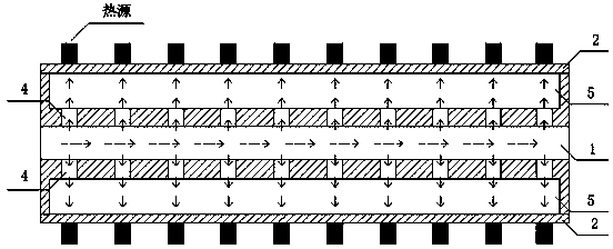
[0011] combine figure 1 , the working principle of the special-shaped channel array jet impinging cold plate of the present invention will be described in detail. From figure 1 It can be seen that the cold plate includes an intermediate layer 1 and an impact chamber 5, the intermediate layer 1 is located between the two impact chambers 5, and is sealed by the cover plate 2 to form a whole. The high heat flux electronic components are respectively arranged on the surface of the cover plate 2 and facing the jet hole 4 . The fluid flows in from one end of the flow channel in the middle layer 1, and then flows out from the other end. When the fluid flows in the flow channel of the middle layer 1 , part of the fluid rushes out from the jet hole 4 and directly hits the inner wall of the cover plate 2 vertically. Since the thickness of the cover plate 2 is...


PUM


Abstract

The invention discloses an abnormal channel array jet flow impact cold plate. The abnormal channel array jet flow impact cold plate comprises impact cavities and a middle layer, wherein the middle layer is located between the two impact cavities. The longitudinal section of a flow channel of the middle layer is triangular, and the area of the section is gradually reduced in the length direction, so that flow of all jet flow holes is equal. Reinforcing ribs are arranged inside the impact cavities, strength of the impact cavities is enhanced, and interference of turbulent flow between the jet flow holes is prevented.

Description

technical field [0001] The invention relates to the field of heat dissipation of electronic devices, in particular to a special-shaped channel array jet impingement cold plate, which is used for uniform temperature heat dissipation of high heat flux density electronic devices. technical background [0002] In the field of electronics industry, the power of electronic devices has increased rapidly, and the heat flux has exceeded 100W / cm 2 . For every ten degrees Celsius increase in temperature, its reliability decreases by 50%. Therefore, it is extremely urgent to control the temperature of high heat flux electronic devices. Common chip cooling methods include air cooling, liquid cooling and phase change cooling. Air cooling is the earliest cooling method, but literature 1 (Research on liquid-cooled cold plates, Xu Dehao, Yang Dongmei, Electromechanical Engineering, 2006, Issue 1, pages 4-6) pointed out that when the heat flux exceeds 5W / cm 2 Sometimes air cooling can...

Claims


Application Information

Patent Timeline
IPC IPC(8): H05K7/20
Inventor 李强宣益民郭磊
Owner NANJING UNIV OF SCI & TECH
Learn More