
vehicle bumper structure

A bumper and vehicle technology, applied to bumpers, vehicle parts, vehicle safety arrangements, etc., can solve the problems of complex interval management and waste of design space, and achieve the effects of reducing bending, effective absorption, and reducing deformation

Inactive Publication Date: 2015-08-19
SUZUKI MOTOR CORP
View PDF6 Cites 0 Cited by
  • Summary
  • Abstract
  • Description
  • Claims
  • Application Information

AI Technical Summary

Problems solved by technology

Therefore, it is necessary to set and set the interval between the bumper fascia and the reinforcement, which leads to problems of wasteful design space and complicated interval management

Method used


Image

  • vehicle bumper structure
  • vehicle bumper structure
  • vehicle bumper structure

Examples


Embodiment Construction

[0033] Hereinafter, the present invention will be described in detail based on the illustrated embodiments.

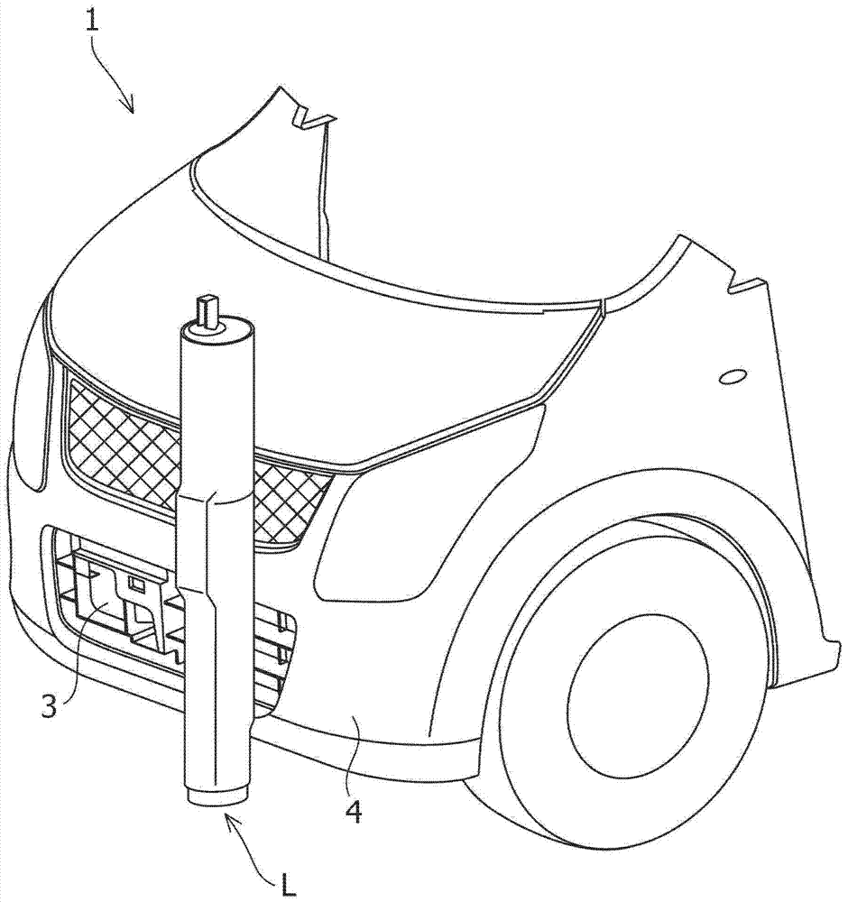
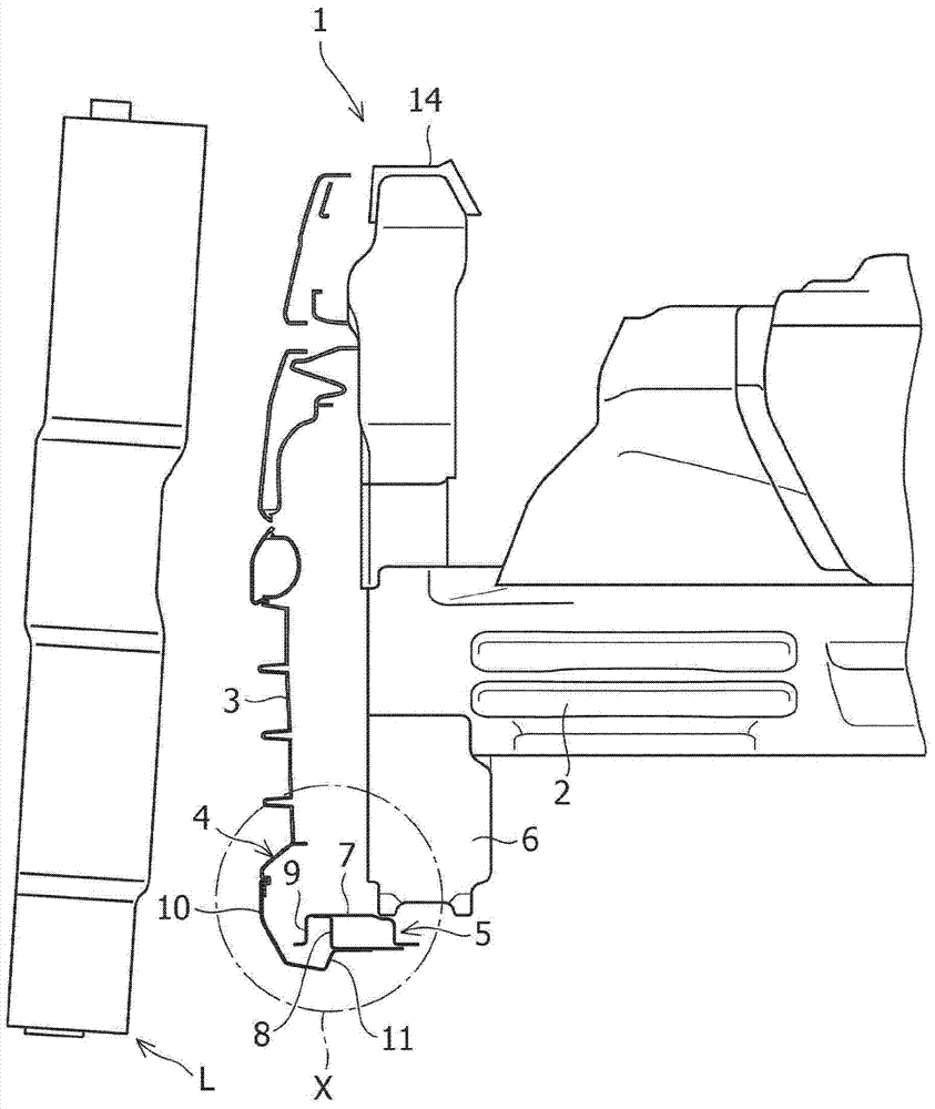
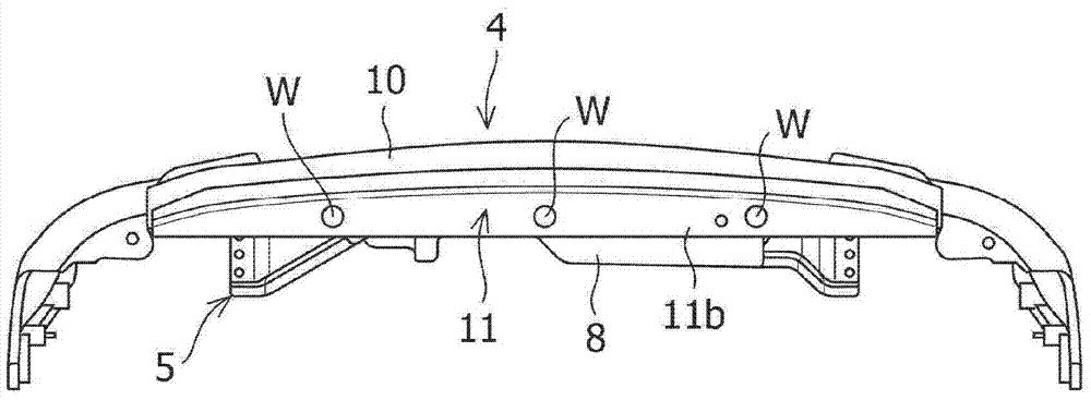
[0034] Figure 1 to Figure 5 A bumper structure of a vehicle according to an embodiment of the present invention is shown.

[0035] Such as figure 1 and figure 2 As shown, the vehicle front 1 to which the bumper structure according to the embodiment of the present invention is applied mainly includes: a pair of left and right apron side members (apron side members) 2 extending along the front-rear direction of the vehicle with an intervening The gap is arranged on the left and right sides of the vehicle width direction; and the resin bumper grille 3 and the front bumper 4 are located in the vehicle front of the skirt side member 2, and the bumper grille 3 is arranged on the back side of the front bumper 4 .

[0036] In the vehicle front portion 1 of the present embodiment, the pedestrian's leg L extending in the vehicle up-down direction is located on the vehicle ...


PUM


Abstract

A vehicle bumper structure in which a sheet-metal member (11) having a shape that conforms with the shape of a bumper is integrally formed on the lower part of a resin bumper (10), wherein: the main part of the sheet-metal member (11) is covered with the resin bumper (10); the lower parts of the sheet-metal member (11) and the resin bumper (10) extend towards the rear end of the vehicle; and, of the resin bumper (10) and the sheet-metal member (11) extending towards the rear end of the vehicle, only the sheet-metal member (11) is attached to the radiator support member (5) on a vehicle body frame.

Description

technical field [0001] The present invention relates to bumper structures for vehicles. Background technique [0002] Generally, at the front end of the vehicle, the lower portion of the lower front bumper and its periphery are arranged so as to protrude toward the front side of the vehicle than the vicinity of the upper front cover (hood). Therefore, when a pedestrian's leg, which is a rod-shaped object, hits the front of the vehicle during a collision or the like, the upper part of the pedestrian's leg tends to move toward the rear of the vehicle, and the leg tends to assume a slanted posture. If the pedestrian's leg hits the front bumper while still leaning, bending stress or shearing stress tends to occur on the pedestrian's leg due to the load from the front side of the vehicle, and the load on the leg (damage grade) tends to increase Big. [0003] Therefore, with the vehicle front having the above structure, when a pedestrian's legs hit the vehicle from the front, it...

Claims


Application Information

Patent Timeline
Patent Type & Authority Patents(China)
IPC IPC(8): B60R19/24B60R19/03
CPCB60R19/18B60R2019/1813B60R19/24
Inventor 大野伸司宫崎章人增田出光
Owner SUZUKI MOTOR CORP
Learn More