Quadrature demodulator
A technology of quadrature demodulation and quadrature detection, which is applied in the directions of measuring devices, oscillation conversion angle demodulation, and phase modulation carrier system, etc. degree error etc.
- Summary
- Abstract
- Description
- Claims
- Application Information
AI Technical Summary
Problems solved by technology
Method used
Image
Examples
no. 1 approach )
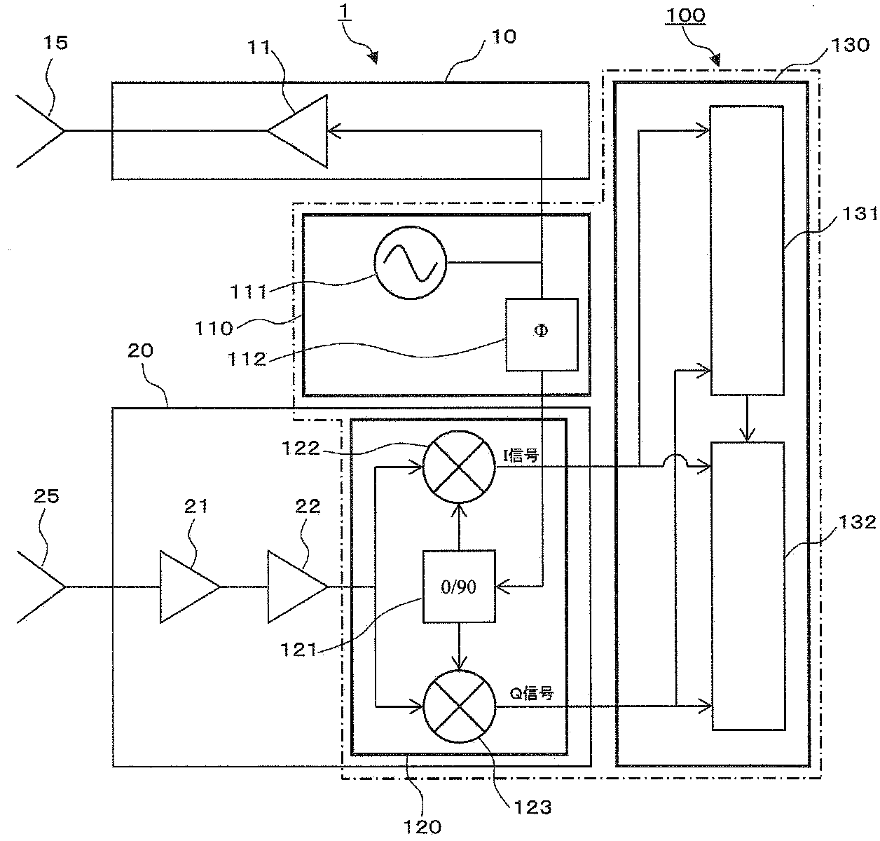
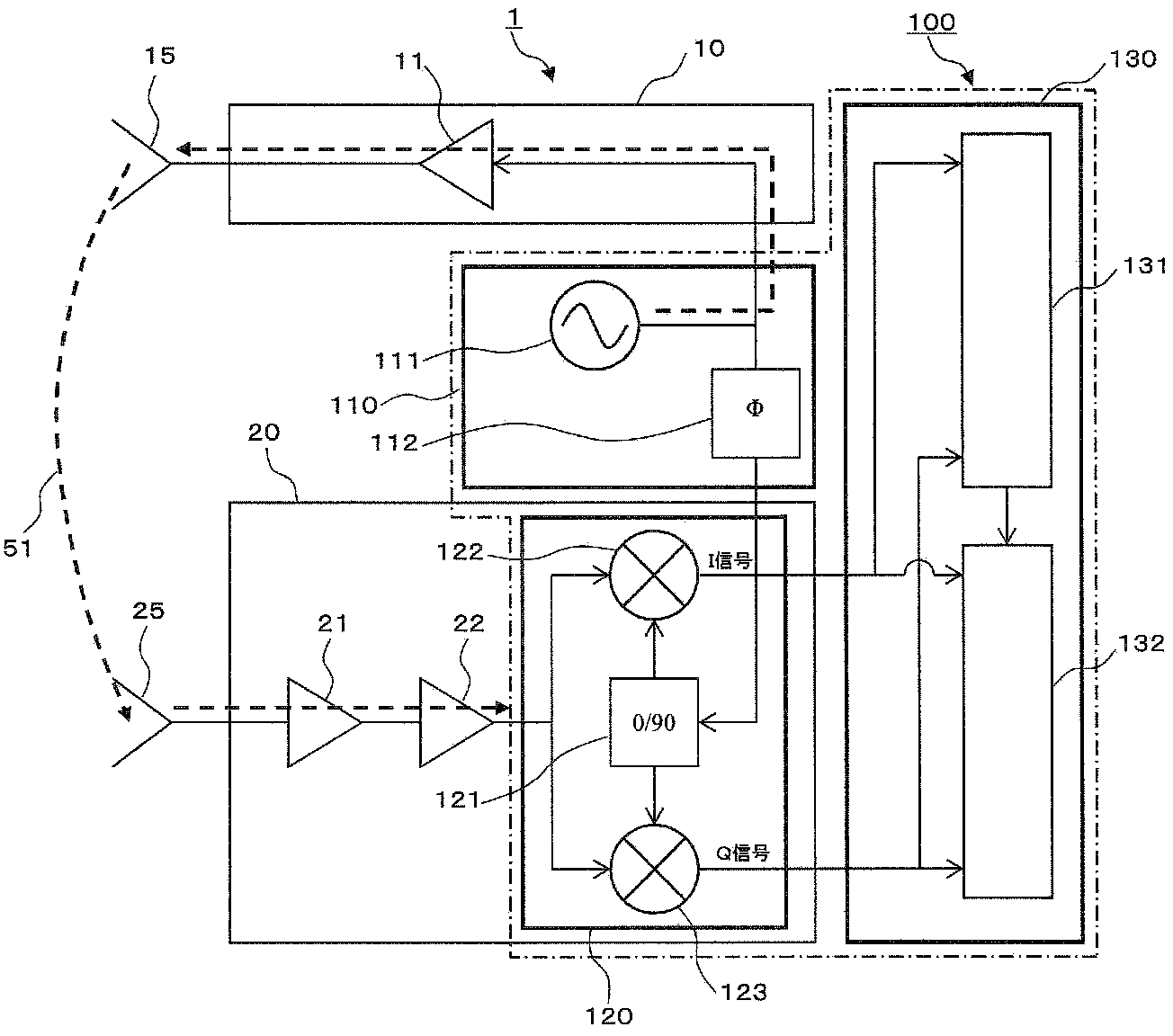
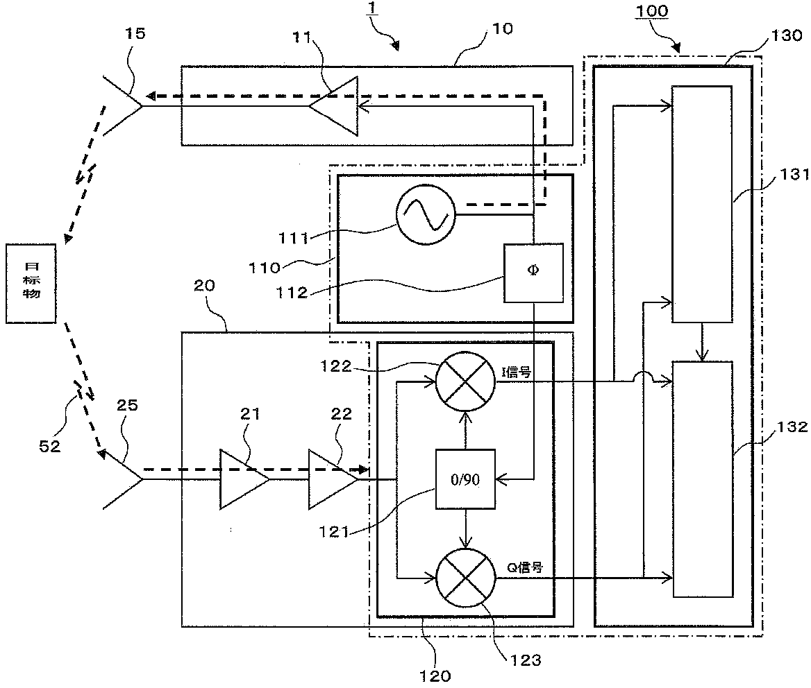
[0030] Below, refer to figure 1 A quadrature demodulation device according to a first embodiment of the present invention will be described. figure 1 It is a block diagram showing the configuration of the radar device 1 including the quadrature demodulation device 100 of the present embodiment. exist figure 1 , the quadrature demodulation device 100 of this embodiment includes: a local oscillator 110 having a local oscillator 111 and a phase adjustment unit 112; quadrature detection unit 120 ; and signal processing unit 130 having quadrature detection error detection unit 131 and quadrature detection error compensation unit 132 .
[0031] Furthermore, the radar device 1 further includes the transmitting unit 10 , the transmitting antenna 15 , the receiving unit 20 , and the receiving antenna 25 in the quadrature demodulation device 100 of the present embodiment. The transmission unit 10 receives a local oscillation signal (LO signal) of a predetermined frequency oscillated ...
no. 2 approach )
[0080] Below, refer to Figure 4 A quadrature demodulation device according to a second embodiment of the present invention will be described. Figure 4 It is a block diagram showing the configuration of the radar device 2 including the quadrature demodulation device 200 of the present embodiment. exist Figure 4 The quadrature demodulation device 200 of the present embodiment further includes a first coupler 213 for distributing the LO signal to the local oscillator 210, and a second coupler 224 before inputting the received signal of the receiving unit 20 to the quadrature detection unit 120. . The first coupler 213 and the second coupler 224 are connected through a designated signal line 214 .
[0081] In the radar device 2 of the present embodiment having the above configuration, a signal path can be formed in which the LO signal output from the local oscillator 111 is distributed by the first coupler 213 and transmitted to the second coupler 224 via the signal line 214...
no. 3 approach )
[0083] Next, a quadrature demodulation apparatus according to a third embodiment of the present invention will be described. Figure 5 It is a block diagram showing the configuration of the radar device 2 including the quadrature demodulation device 300 of the present embodiment. exist Figure 5 The quadrature demodulation device 300 of this embodiment has two quadrature detection units, a first quadrature detection unit 320a and a second quadrature detection unit 320b, as quadrature detection units. Also, a signal distribution unit 314 is provided in the local oscillator 310 to distribute the LO signal output from the local oscillator 111 and input it to the respective phase shifters 121 of the first quadrature detection unit 320a and the second quadrature detection unit 320b. In the signal distributing section 314, the LO signal output to the first quadrature detection section 320a and the LO signal output to the second quadrature detection section 320b are output with a ph...
PUM
 Abstract
Description
Claims
Application Information
 - R&D
- Intellectual Property
- Life Sciences
- Materials
- Tech Scout
- Unparalleled Data Quality
- Higher Quality Content
- 60% Fewer Hallucinations
Browse by: Latest US Patents, China's latest patents, Technical Efficacy Thesaurus, Application Domain, Technology Topic, Popular Technical Reports.
© 2025 PatSnap. All rights reserved.Legal|Privacy policy|Modern Slavery Act Transparency Statement|Sitemap|About US| Contact US: help@patsnap.com


