Layered micro-channel reactor with uniformly distributed micro-channel flow velocities

A microchannel reactor, stacked technology, applied in chemical instruments and methods, chemical/physical/physicochemical processes, chemical/physical processes, etc., can solve high manufacturing costs, large flow pressure drop loss, high flow path system Power and other issues, to achieve the effect of improving the uniformity of flow velocity distribution, improving heat and mass transfer performance, and reducing pressure loss

Inactive Publication Date: 2014-12-17
ZHEJIANG UNIV
View PDF2 Cites 11 Cited by
  • Summary
  • Abstract
  • Description
  • Claims
  • Application Information

AI Technical Summary

Problems solved by technology

The microchannel heat exchanger effectively solves the problem of excessive fluid pressure drop loss in the microchannel reactor, but the microchannel heat exchanger has a complicated flow splitting structure and high manufacturing costs
[0006] To sum up, the flow rate distribution of the existing traditional microchannel reactor is not high, and its heat and mass transfer efficiency is limited. In addition, the fluid pressure loss is too large, which requires a higher flow system power

Method used


Image

  • Layered micro-channel reactor with uniformly distributed micro-channel flow velocities
  • Layered micro-channel reactor with uniformly distributed micro-channel flow velocities
  • Layered micro-channel reactor with uniformly distributed micro-channel flow velocities

Examples


Embodiment 1

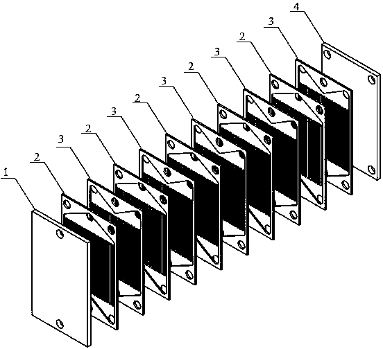
[0038] Figure 6 It is a schematic diagram of the structure of a microchannel reactor for methanol steam autothermal reforming to produce hydrogen. The microchannel reactor is coupled with methanol steam reforming reaction and methanol catalytic combustion reaction. The heat required for methanol steam reforming reaction is provided by the heat released by methanol combustion, mainly including inlet cover plate 1 and two first reaction plates 2. A second reaction plate 3 and an outlet cover plate 4; wherein:

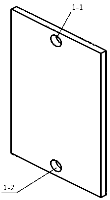
[0039] The inlet cover plate 1 is a rectangular stainless steel plate with a first reaction fluid inlet 1-1 processed in the middle of the top, a second reaction fluid inlet 1-2 in the middle of the bottom of the inlet cover 1, and the first reaction fluid inlet 1-1 through Methanol and water vapor are fed in, which is a channel for methanol steam reforming reaction, and methanol and air are introduced into the second reaction fluid inlet 1-2, which is a channel for met...

Embodiment 2

[0051] The structure of the microchannel reactor of this embodiment is basically the same as that of Example 1, except that the microchannel reactor of this embodiment is used as a heat exchanger. The two working medium fluids entering the microchannel reactor are cold fluid and hot fluid, which enter from one inlet and flow out from two outlets, which can improve the uniformity of the flow velocity distribution of the microchannel array, reduce the temperature gradient, and improve the efficiency of the heat exchanger , The shunt structure is also beneficial to reduce the pressure drop.


PUM


Abstract

The invention discloses a layered micro-channel reactor with uniformly distributed micro-channel flow velocities. The layered micro-channel reactor comprises an inlet cover plate, first reaction plates, second reaction plates and an outlet cover plate. Micro-channel arrays are machined on the first reaction plates and the second reaction plates, and the first reaction plates and the second reaction plates are alternately overlaid between the inlet cover plate and the outlet cover plate which are oppositely placed. Reaction fluid flows into the micro-channel arrays from an inlet and flows out of two outlets, the flow velocity distribution uniformity of the reaction fluid in the micro-channel arrays is improved, and accordingly the reaction efficiency of the micro-channel reactor can be effectively improved. Besides, pressure loss caused when the fluid flows through the micro-channel reactor can be effectively reduced owing to a distribution structure with the single inlet and the two outlets. The multiple layers of first reaction plates and the multiple layers of second reaction plates are overlaid, so that the reaction scope can be expanded, and the reaction efficiency can be improved. Compared with an existing micro-channel reactor with a single inlet and a single outlet, the layered micro-channel reactor has the advantages that the reaction uniformity can be improved, and the layered micro-channel reactor is high in reaction efficiency and low in fluid pressure loss.

Description

technical field [0001] The invention relates to a microfluidic device, in particular to a laminated microchannel reactor with uniform channel flow velocity for microchemical reactions. technical background [0002] Microchannel reactor is a micro-chemical reaction system with a unit reaction interface scale of micron. Compared with conventional macro-reactors, micro-reactors have the following advantages: (1) Higher specific surface area, so heat transfer, mass transfer It is strengthened, which is conducive to the rapid and uniform mixing of fluids and isothermal operation; (2) the reaction is safer, and the strengthening of the transfer process makes the reaction process in the reactor easier to control; (3) unique flow characteristics, the fluid flow is usually laminar Flow, with strong directionality, symmetry and order, is conducive to accurate theoretical description and simulation of the process; (4) high-throughput screening of catalysts. In recent years, with the c...

Claims


Application Information

Patent Timeline
Patent Type & Authority Patents(China)
IPC IPC(8): B01J19/00
Inventor 梅德庆梁灵威钱淼娄心洋陈子辰
Owner ZHEJIANG UNIV
Why Eureka
Try Eureka