
Fluidize adsorption continuous refrigeration system and method thereof

A refrigeration system and fluidization technology, applied in the field of fluidized adsorption continuous refrigeration system, can solve the problems of small thermal conductivity, increased heat loss, large contact thermal resistance between adsorbent and heat transfer metal wall, etc.

Inactive Publication Date: 2008-03-12
ZHENGZHOU UNIV
View PDF0 Cites 4 Cited by
  • Summary
  • Abstract
  • Description
  • Claims
  • Application Information

AI Technical Summary

Problems solved by technology

[0002] At present, adsorption refrigeration technology is increasingly becoming the research focus of people, but there are two major problems in this technology: 1. The porous characteristic of the adsorbent itself makes the thermal conductivity small; 2. The contact thermal resistance between the adsorbent and the heat transfer metal wall Larger, when the cold and hot fluid alternately pass through the partition wall heat exchanger (shell-and-tube, spiral plate, plate-fin type) to heat or cool the adsorbent to achieve desorption and adsorption of the refrigerant, the sensible heat of the heat exchanger and the adsorbent itself Variations add additional heat loss
[0004] However, the following problems are: the diffusion resistance of the refrigerant (adsorbate) in the solid adsorbent is relatively large, especially when the adsorbent is solidified to improve the heat transfer coefficient of the adsorbent, and the adsorption resistance of the adsorbent after solidification increase, the thickness of the adsorbent is required not to be too large, and generally needs to be controlled below 5mm
[0007] Although scholars at home and abroad have proposed a rotary adsorption refrigeration system, it still cannot completely overcome the above problems.

Method used


Image

  • Fluidize adsorption continuous refrigeration system and method thereof

Examples


Embodiment Construction

[0027] The technical solutions of the present invention will be described in further detail below through specific implementation methods.

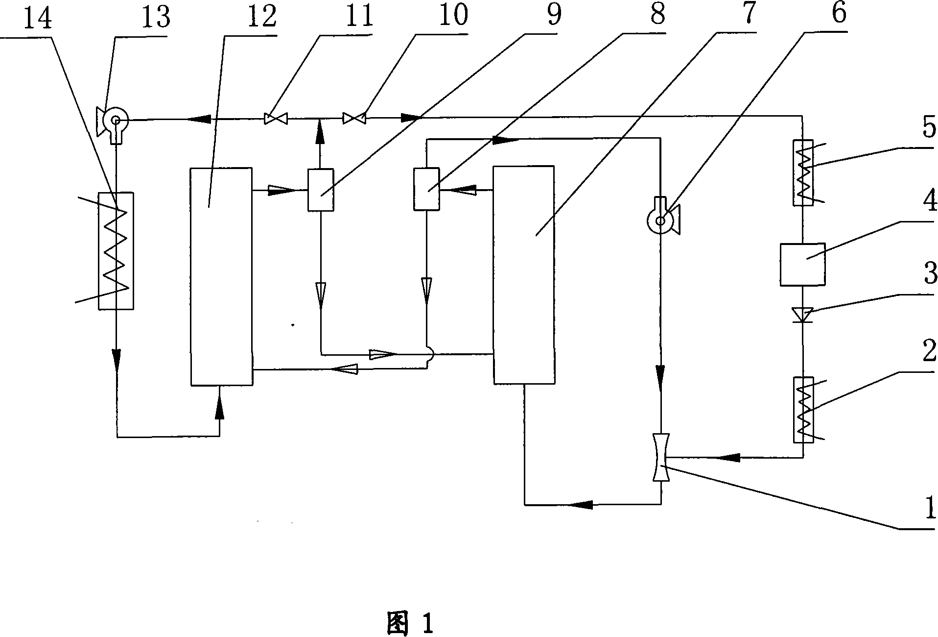
[0028] As shown in Figure 1: a fluidized adsorption continuous refrigeration system, including a refrigeration part that absorbs or releases heat to the outside, an adsorption part that makes the adsorbent absorb the refrigerant and cools down, and heats up the adsorbent and desorbs the refrigerant The desorption part;

[0029] The refrigerating part includes an evaporator 2, a throttle valve 3, a liquid storage tank 4 and a condenser 5;

[0030] The adsorption part includes a venturi tube 1, a compressor 6, an adsorption bed 7 and a gas-solid separator 8;

[0031] The desorption part includes a gas-solid separator 9, a vacuum valve 10, a vacuum valve 11, a desorption bed 12, a heat exchanger 14 and a compressor 13;

[0032] Wherein, one end of the vacuum valve 11 is connected to one end of the compressor 13 through a pipeline, the othe...


PUM


Abstract

The invention provides a fluidized adsorption continuous refrigeration system and its method, wherein the system comprises a refrigeration part composed of an evaporator (2), a throttle valve (3), a liquid storage tank (4) and a condenser (5), an adsorption part resulting in that an adsorbent adsorbs a refrigerant and is cooled down by the refrigerant, and a desorption part resulting in that the adsorbent is heated up and the refrigerant is desorbed; the adsorption part comprises a venturi tube (1), a compressor (6), an adsorption bed (7) and a gas-solid separator (8); the desorption part comprises a gas-solid separator (9), a vacuum valve (10), a vacuum valve (11), a desorption bed (12), a heat exchanger (14) and a compressor (13); the method comprises a heat-absorbing temperature rise, desorption, circulation, refrigeration, adsorption, recirculation and other steps. The system directly implements heat exchange and material exchange with the refrigerant and the adsorbent, which realizes the simultaneous implementation of heat transfer and mass transfer in order to result in that the capacity of heat transfer and mass transfer is strengthened, and realizes the continuous refrigeration or heating and improves the heat utilization efficiency.

Description

technical field [0001] The invention relates to a fluidized adsorption continuous refrigeration system and a method thereof, belonging to the technical field of adsorption refrigeration. Background technique [0002] At present, adsorption refrigeration technology is increasingly becoming the research focus of people, but there are two major problems in this technology: 1. The porous characteristics of the adsorbent itself make the thermal conductivity small; 2. The contact thermal resistance between the adsorbent and the heat transfer metal wall Larger, when the cold and hot fluid alternately pass through the partition wall heat exchanger (shell-and-tube, spiral plate, plate-fin type) to heat or cool the adsorbent to achieve desorption and adsorption of the refrigerant, the sensible heat of the heat exchanger and the adsorbent itself Variations add additional heat loss. [0003] At present, the main way to solve this problem is to solidify the adsorbent inside or outside t...

Claims


Application Information

Patent Timeline
IPC IPC(8): F25B15/00F25B37/00
CPCY02B30/62Y02B30/64Y02A30/27Y02B30/00
Inventor 魏新利孟祥睿马新灵
Owner ZHENGZHOU UNIV
Learn More