Magnetic field array auxiliary resistance spot welding device and method for sheet metal materials

An auxiliary resistance, sheet metal technology, applied in resistance welding equipment, metal processing equipment, welding equipment, etc., can solve the problems of unmatched magnetic field mode conversion, low solute, low heat transfer rate, and low force on molten metal. Achieve the effect of improving heat and mass transfer capacity, improving comprehensive mechanical properties, and increasing the number of equiaxed crystals

Pending Publication Date: 2022-02-15
BEIJING UNIV OF TECH
View PDF6 Cites 4 Cited by
  • Summary
  • Abstract
  • Description
  • Claims
  • Application Information

AI Technical Summary

Problems solved by technology

[0005] 1) The magnetic field mode is single, and the external magnetic field causes the molten metal to be stressed in the same direction in the circumferential direction and has no radial force, and the solute and heat transfer rates in the radial direction of the nugget are low;
[0006] 2) Compared with that near the center of the nugget, the strength of the horizontal component of the magnetic field is lower near the edge of the nugget, so the force on the molten metal near the edge of the nugget is lower, and the grain refinement effect is weaker;
[0007] 3) The conversion of the magnetic field mode does not really match the changes in the cooling and solidification stage of the nugget. The nugget has not cooled to the point of solidification when it is converted to the auxiliary stirring current. At this time, the role of the magnetic force is still to expand the size of the nugget. Solidification begins after a period of auxiliary stirring current, and at this time, the magnetic force has the effect of refining grains

Method used


Image

  • Magnetic field array auxiliary resistance spot welding device and method for sheet metal materials
  • Magnetic field array auxiliary resistance spot welding device and method for sheet metal materials
  • Magnetic field array auxiliary resistance spot welding device and method for sheet metal materials

Examples


Embodiment 1

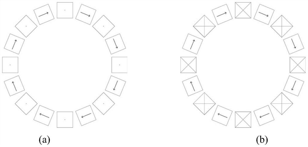
[0064] The resistance spot welding process in this example is divided into three stages: 0~t 1 is the preload stage, t 1 ~t 2 is the heating and welding stage, t 2 ~t 4 for the holding phase. Apply a stronger welding current I during the heating welding phase 1 , and the extension current i 1 , to drive the metal liquid phase to move in a circumferential direction, thereby increasing the diameter of the nugget; in the pressure-holding stage, a weaker auxiliary current I is applied 2 , and the stirring current i 2 , the synchronous system 8 takes the relative change speed of dynamic resistance as the criterion, converts and increases the nugget-type magnetic field and stirs the nugget-type magnetic field, increases the nugget with maximum efficiency, and strengthens the stirring effect, thereby refining the grain structure and eliminating components Segregation. During the entire resistance spot welding process, the upper and lower electrodes apply pressure F to the wor...

Embodiment 2

[0073] The workpiece 8 to be welded in this embodiment is a 6061 aluminum alloy with a plate thickness of 2mm+2mm.

[0074] The electrode pressure F in this embodiment is 3 kN.

[0075] The preload time t in this embodiment 1 , is 200 ms, welding time t 2150 milliseconds, holding time t 4 for 600 milliseconds.

[0076] The heating welding current I in this embodiment 1 , is 24000 amperes, auxiliary stirring current I 2 for 1600 amps.

[0077] Excitation current i in this example 1 , is 1800 mA, excitation current i 2 It is 4000 mA, all of which are DC waves.

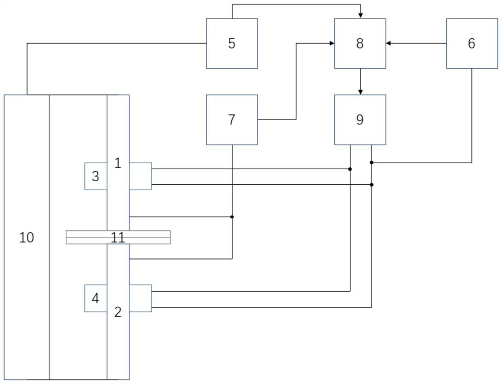
[0078] The working process of this example is as follows: the workpiece 11 to be welded is placed on the welding fixture, and at 0 o'clock, it enters the preloading stage, and the resistance spot welding torch 10 applies a force F to the workpiece 11 to be welded through the upper and lower motors, and keeps The changing electrode force F remains unchanged until the end of the pressure holding process; at t 1 W...


PUM


Abstract

The invention relates to a magnetic field array auxiliary resistance spot welding device and method for sheet metal materials. According to the device and method of the invention, on the basis of basic magnetic control resistance spot welding equipment, an exciting coil is replaced by a Halbach magnetic field array, a dynamic feedback system is additionally arranged, the system and the equipment can convert the magnetic field array; a nugget expansion mode magnetic field is formed in the pre-solidification stage of the resistance spot welding process in a non-contact mode, a circumferential acting force is applied to liquid metal in a resistance spot welding nugget to increase the size of a welding spot; the moment when the nugget begins to solidify is truly judged through the dynamic feedback system; the magnetic field array mode is converted when the nugget begins to solidify, a stirring enhanced magnetic field is formed; crystalline grains are refined, chemical components are homogenized, and crack sensitivity is improved; and finally, the comprehensive mechanical performance of a resistance spot welding joint is improved.

Description

technical field [0001] The invention relates to a device in the field of welding technology, in particular to a magnetic field array assisted resistance spot welding system. Background technique [0002] The invention relates to a device in the field of welding technology, in particular to a magnetic field array assisted resistance spot welding system. [0003] As an effective method to improve the primary crystallization structure during metal solidification, electromagnetic stirring has been successfully applied in arc welding, casting and other fields. The principle is to make the high-temperature metal magnetic fluid flow regularly and at high speed through the non-contact action of the electromagnetic field, thereby affecting and changing the primary crystallization process of the molten metal. The action of the external magnetic field can refine the primary crystallization structure of the weld metal and improve the strength of the joint. Extensive research on magnet...

Claims


Application Information

Patent Timeline
Patent Type & Authority Applications(China)
IPC IPC(8): B23K11/11B23K11/36
CPCB23K11/115B23K11/36
Inventor 李红闫维嘉张禹栗卓新李国栋
Owner BEIJING UNIV OF TECH
Why Eureka
Try Eureka