Full-counterflow enclosed cooling column with air intake at upper and lower part

A closed cooling tower, counter-flow technology, applied in the direction of water shower cooler, direct contact heat exchanger, heat exchanger type, etc., can solve the problem of small air circulation area, low heat transfer efficiency, spray water and fluid in the pipe Uneven temperature difference and other problems, to achieve uniform water distribution, increase the flow area, and improve the effect of heat and mass transfer

Inactive Publication Date: 2008-12-10
UNIV OF SHANGHAI FOR SCI & TECH
View PDF0 Cites 3 Cited by
  • Summary
  • Abstract
  • Description
  • Claims
  • Application Information

AI Technical Summary

Problems solved by technology

[0004] The purpose of the present invention is to disclose a kind of upper and lower air inlet full counterflow closed cooling tower, which overcomes the small air circulation area and the temperature difference between spray water and air, spray water and fluid in the pipe in the existing counter flow closed cooling tower Disadvantages such as extremely uneven flow and low heat transfer efficiency

Method used


Image

  • Full-counterflow enclosed cooling column with air intake at upper and lower part
  • Full-counterflow enclosed cooling column with air intake at upper and lower part

Examples


Embodiment Construction

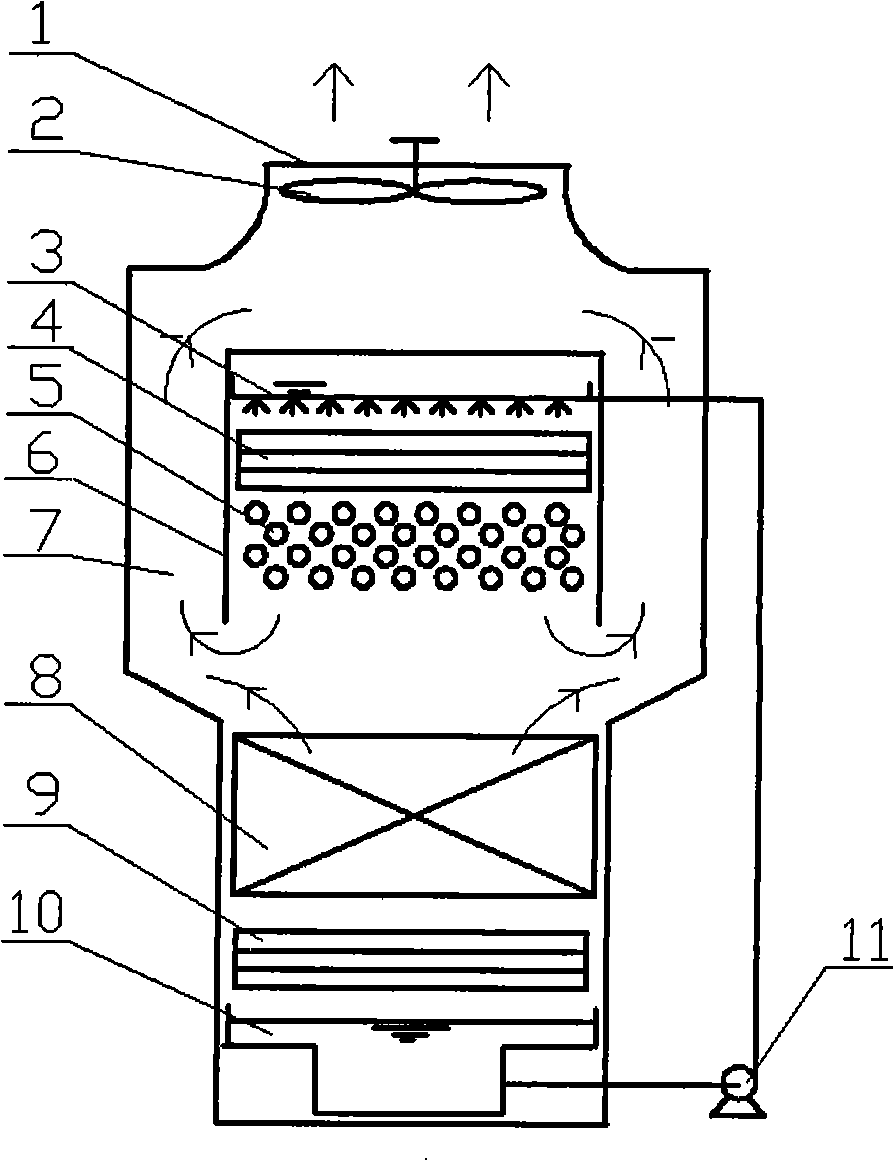
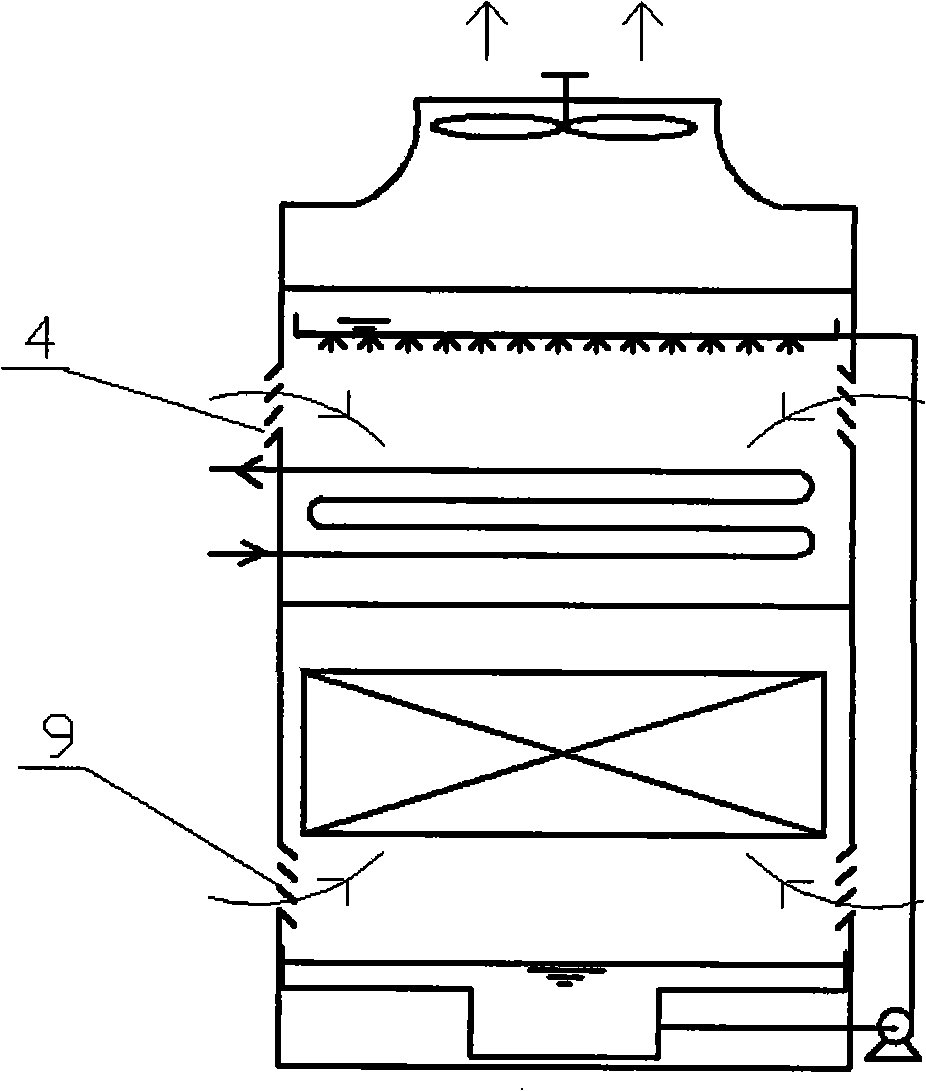
[0013] The upper and lower air inlet full counterflow closed cooling tower, which includes: air outlet 1, fan 2, water distributor 3, upper air inlet 4, tube bundle 5, channel partition 6, exhaust channel 7, packing 8, lower air inlet 9 , water collecting tray 10, water pump 11; tube bundle 5 is arranged in the upper area of ​​the closed cooling tower, filler 8 is arranged in the lower area of ​​the cooling tower, fan 2 is at the top of the tower body, water collecting tray 10 is at the bottom of the tower body, and the tube bundle is arranged above There is a water distributor 3, and the water collecting tray 10 is connected to the water distributor 3 through the water pump 11; the upper and lower two air inlets 4 and 9 are respectively opened on the upper and lower parts of the two sides of the cooling tower, and the other two air inlets are not opened. The side surface and the channel partition 6 form an exhaust channel 7, which communicates with the central area of ​​the to...


PUM


Abstract

The invention relates to complete countercurrent closed cooling tower with air inlets on an upper and a lower parts. A tube bundle is arranged on the upper part of the closed cooling tower, and fillers are arranged on the lower part. A fan is arranged on the top of the tower. A water collection disc is arranged on the bottom of the tower. The upper part of the tube bundle is provided with a water distributor. The water collection disc is connected with the water distributor by a pump. The upper and the lower parts of the two lateral sides of the cooling tower are separately provided with two air inlets-the upper air inlet and the lower air inlet. The other two lateral sides and a channel separator form an air exhaust channel. The air that enters into the cooling tower from the upper air inlet and flows downwards, after the air passes through the tube bundle, the air meets the air that enters into the cooling tower from the lower air inlet, flows upwards and passes through the fillers. The direction of the air is changed in the middle of the cooling tower. The air flows upwards through the air exhaust channel and is discharged from the top of the cooling tower. The air in the fillers flows along a reverse direction with the spray water which flows from top to bottom. The air in the tube buddle flows along a same direction with the spray water and flow along a reverse direction with the cooled fluid in the tube buddle. The countercurrent closed cooling tower can use pool typed water distribution system. The closed cooling tower can increase the flow area and the flow quantity of the air. The water distribution is uniform, and the effects of the heat transfer and mass transfer are improved.

Description

technical field [0001] The invention relates to a new type of closed cooling tower, in particular to a closed cooling tower in which air is fed into the upper and lower parts of the cooling tower, and the wind direction and the flow of fluid in the tube bundle and filler in the tower are countercurrent and a pool type water distribution system can be used. tower. Background technique [0002] The cooling tower is mainly a device that directly contacts the spray water with the air and completes the heat exchange through the evaporation and heat dissipation of the spray water. It is divided into an open cooling tower and a closed cooling tower. For a closed cooling tower, the fluid to be cooled flows in the tubes, and the spray water flows through the heat transfer surface of the tube bundle to take away the heat of the fluid in the tubes; the air contacts the spray water, and the heat of the spray water is taken away by the evaporation of the spray water. Cooling towers are ...

Claims


Application Information

Patent Timeline
Patent Type & Authority Applications(China)
IPC IPC(8): F28C1/02
Inventor 欧阳新萍章立新刘妮李辉
Owner UNIV OF SHANGHAI FOR SCI & TECH
Why Eureka
Try Eureka