Compound clamping mechanism of machine tool

A clamping mechanism and machine tool technology, applied in the direction of clamping, metal processing mechanical parts, supports, etc., can solve the problems of long auxiliary time for parts processing, low versatility of special fixtures, high labor intensity, etc., and achieves simple structure and design. Reasonable and the effect of reducing labor intensity

Inactive Publication Date: 2013-12-04
WUXI YICHEN MOLD TECH
View PDF4 Cites 13 Cited by
  • Summary
  • Abstract
  • Description
  • Claims
  • Application Information

AI Technical Summary

Problems solved by technology

[0003] Aiming at the problems caused by the existing clamping mechanism, such as high labor intensity, long auxiliary time for parts processing, and low versatility caused by special fixtures, the invention provides a composite clamping mechanism for machine tools

Method used


Image

  • Compound clamping mechanism of machine tool
  • Compound clamping mechanism of machine tool
  • Compound clamping mechanism of machine tool

Examples


Embodiment 1

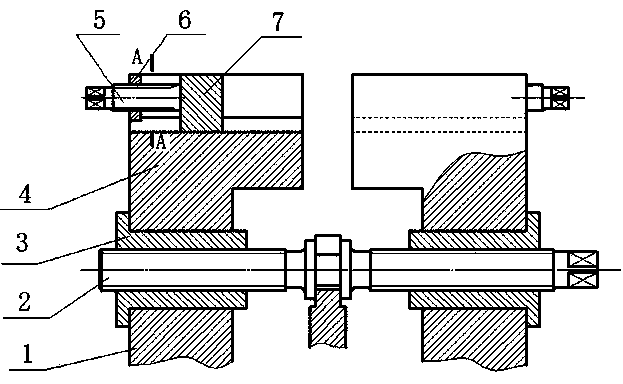
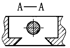
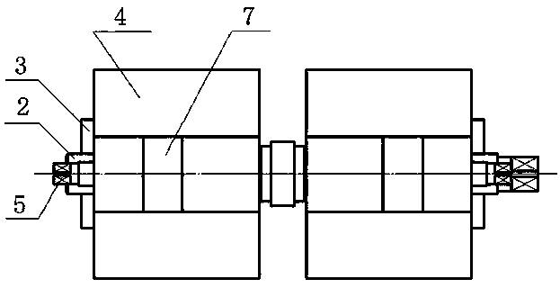
[0022] Such as figure 1 , figure 2 , image 3 As shown, the composite clamping mechanism of the machine tool includes a slide rail 1, a large adjusting screw 2, a moving block 3, a large clamping block 4, a small adjusting screw 5, a fixed block 6 and a small clamping block 7, and the upper end of the slide rail 1 is stuck on the On the concave edge of the lower end of the moving block 3, the large adjusting screw 2 is engaged with the moving block 3, the lower end of the large clamping block 4 is pressed on the concave edge of the upper end of the moving block 3, and the upper end of the large clamping block 4 is set There is a groove, the vertical section of the upper part of the groove is rectangular, the lower part of the groove is a dovetail groove, the fixed block 6 is fixed on the side end of the groove of the large clamping block 4, and the upper end of the small clamping block 7 It is flush with the upper end of the groove of the large clamping block 4, and the low...


PUM


Abstract

The invention discloses a compound clamping mechanism of a machine tool, which belongs to the field of machine tool fixtures. The compound clamping mechanism of the machine tool comprises a sliding rail, a large adjusting screw rod, a moving block, a large clamping block, a small adjusting screw rod, a fixed block and a small clamping block, wherein the upper end of the sliding rail is clamped on a flange at the lower end of the moving block; the large adjusting screw rod is engaged with the moving block; the lower end of the small clamping block is embedded into a dovetail groove at the lower end of a groove of the large clamping block; the small adjusting screw rod is engaged with the fixed block; one end of the small adjusting screw rod is fixedly connected with the small clamping block. The compound clamping mechanism of the machine tool solves the problems that according to the existing clamping mechanism, the labor intensity is large, the auxiliary time for parts processing is long, the universality is low due to a special fixture, and the like, and has the advantages of simple structure, reasonable design, and easiness in manufacturing.

Description

technical field [0001] The invention belongs to the field of machine tool clamps, and in particular relates to a clamping mechanism for fixing workpieces, and more specifically relates to a composite clamping mechanism for machine tools. Background technique [0002] In the machinery manufacturing industry, lathes are widely used to process various parts, and reliable positioning of the workpiece is required during processing. For the processing of workpieces with single piece, small batch and large workload, generally, the positioning and clamping can be realized directly on the machine tool table by adjusting the fixture, and then the position of the part can be determined by setting the processing coordinate system; For a certain batch of parts, it is necessary to reduce labor intensity, reduce part processing auxiliary time, and improve production efficiency by selecting relevant special fixtures. However, when using a special fixture for processing, it is usually neces...

Claims


Application Information

Patent Timeline
Patent Type & Authority Applications(China)
IPC IPC(8): B23Q3/06
Inventor 钱根来李康魏鑫夏守忠陈微霞丁亭
Owner WUXI YICHEN MOLD TECH
Why Eureka
Try Eureka