Assembling positioning jig

A technology for positioning fixtures and positioning holes, which is applied in lamination devices, layered products, lamination, etc., and can solve problems such as deflection, excessive clearance, and assembly deformation.

Inactive Publication Date: 2013-12-04
昆山濡鑫光电科技有限公司
View PDF6 Cites 16 Cited by
  • Summary
  • Abstract
  • Description
  • Claims
  • Application Information

AI Technical Summary

Problems solved by technology

[0002] At present, computers have been widely used and popularized. In order to protect the display of the computer, people generally install a display protection screen on t

Method used


Image

  • Assembling positioning jig
  • Assembling positioning jig

Examples


Embodiment 1

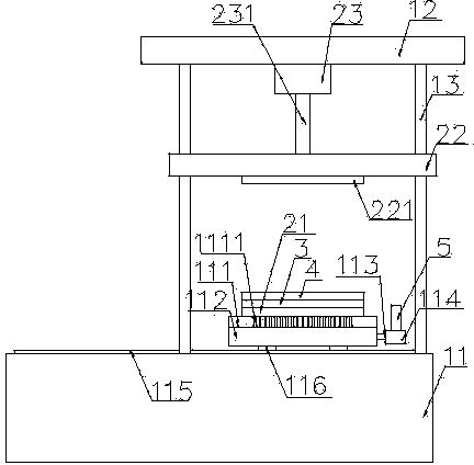
[0021] see figure 1 and figure 2 , as shown in the legend therein, an assembly positioning jig for installing the display protection screen 4 on the display front frame 3, including a frame and a pressing device, the frame includes a base 11, a Top plate 12 and four guide posts 13; the pressing device includes a positioning base plate 21, a pressing plate 22 and a cylinder 23; the guide post 13 vertically connects the base 11 and the top plate 12, and the pressing plate 22 covers It is arranged on the guide post 13 and moves up and down along the guide post 13; the cylinder 23 is fixed on the top plate 12 and connected to the pressing plate 22 through the driving of the cylinder piston 231, and the pressing of the pressing plate 22 A foam buffer gasket 221 is attached to the surface.

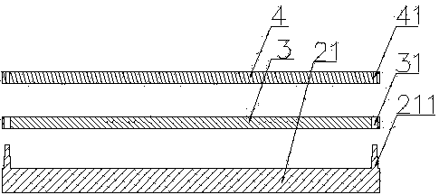
[0022] The display front frame 3 and the display protection screen 4 are respectively provided with two first positioning holes 31 and two second positioning holes 41, and the positioning bo...

Embodiment 2

[0029] The rest are the same as the first embodiment, except that the cylinder is a hydraulic cylinder.

Embodiment 3

[0031] The rest are the same as the first embodiment, the difference is that the cylinder is a rotary lifting device.


PUM


Abstract

The invention discloses an assembling positioning jig which is used for installing a protection screen of a display on a display front frame and comprises a machine frame and a pressing device. The assembling positioning jig is high in positioning accuracy and accurate in installation and achieves mechanical automation.

Description

technical field [0001] The invention relates to an assembling and positioning jig, in particular to an assembling and positioning jig for installing a display protective screen on the front frame of the display. Background technique [0002] At present, computers have been widely used and popularized. In order to protect the display of the computer, people generally install a display protection screen on the front frame of the display. The traditional assembly is assembled by manual alignment. Deformation and deflection and other issues. Contents of the invention [0003] In order to solve the above problems, the present invention provides an assembly and positioning jig with high positioning accuracy, accurate installation and automatic mechanical assembly. [0004] In order to achieve the above object, the present invention provides the following technical solutions: an assembly positioning jig for installing the display protection screen on the front frame of the displ...

Claims


Application Information

Patent Timeline
IPC IPC(8): B32B37/00
Inventor 吕俊民
Owner 昆山濡鑫光电科技有限公司
Why Eureka
Try Eureka