Material conveying device

A technology for conveying devices and materials, applied in conveyors, conveyor objects, transportation and packaging, etc., can solve the problems of increasing the temperature of the drive motor, affecting the efficiency of material processing, and increasing the load, so as to improve the conveying efficiency and facilitate the concentration , the effect of easy implementation

Active Publication Date: 2013-12-04
ZHANGJIAGANG XIAFEI PLASTIC
View PDF5 Cites 11 Cited by
  • Summary
  • Abstract
  • Description
  • Claims
  • Application Information

AI Technical Summary

Problems solved by technology

[0002] There are many forms of material conveying, among which the belt conveying structure is the most commonly used, but it is difficult to meet the feeding requirements for different product belt conveying structures, for example, perfume bottle caps, nozzles, etc., during the feeding process, Bottle caps and nozzles are fed in batches, which are easy to fall off from both sides of the belt, resulting in the inability of the materials to be conveyed on the belt in a concentrated manner. At the same time, when they are conveyed to the processing area, the materials are also scattered, which is not conducive to the feeding of processing equipment. , directly affects the efficiency of material processing. In addition, the tension of the conveyor belt is also very important. If the conveyor belt is too loose, it is easy to cause the conveyor belt to slip. At the same time, if the conveyor belt is too tight, it will easily cause the temperature of the drive motor to rise and the load to increase. , therefore, brings great inconvenience to the actual operation

Method used


Image

  • Material conveying device
  • Material conveying device

Examples


Embodiment Construction

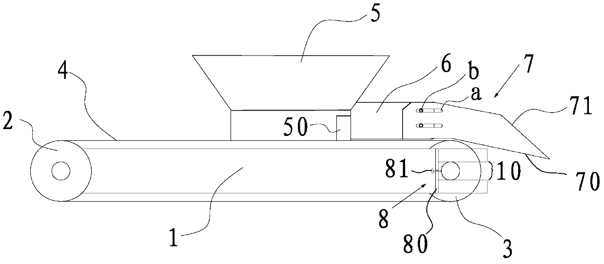
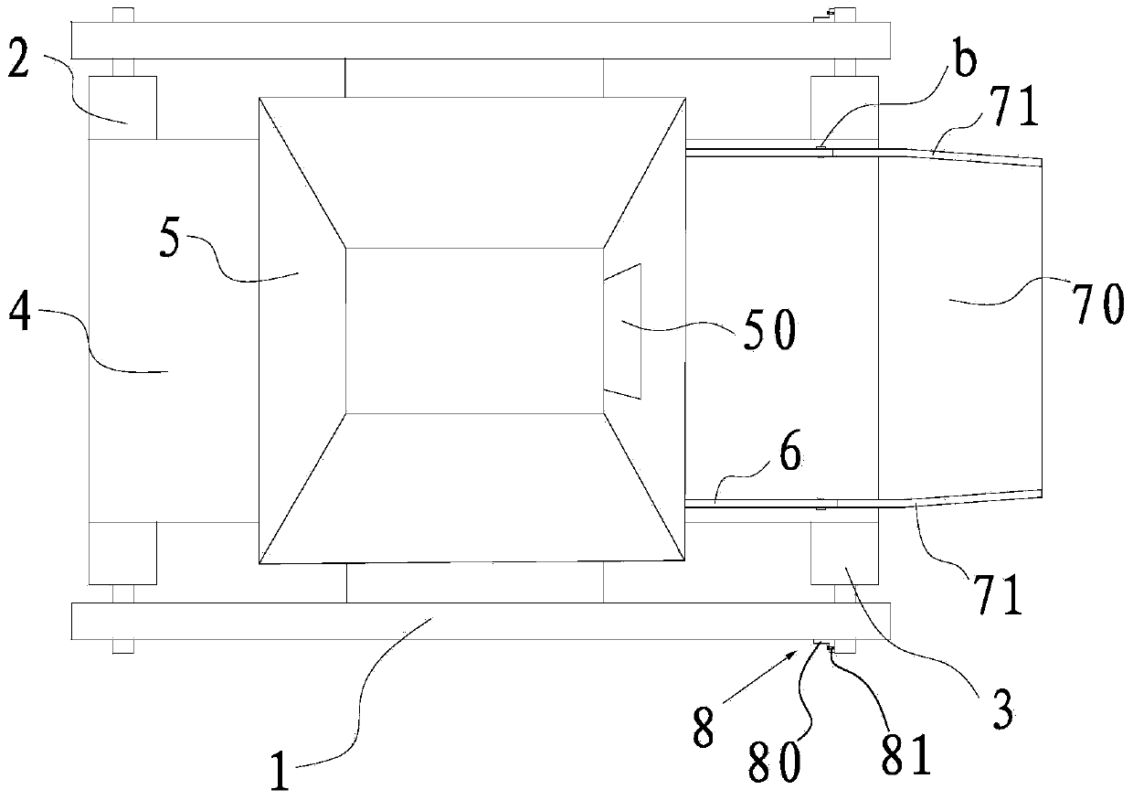
[0018] Such as figure 1 and figure 2 As shown, a material conveying device provided in this embodiment includes a first roller 2 and a second roller 3 which are arranged at both ends of the frame 1 and can rotate around their own axes, and are sheathed on the first roller. 2 and the conveyor belt 4 on the second roller 3, the drive mechanism (not shown) that drives the first roller 2 or the second roller 3 to rotate, and meanwhile, the conveying device in this example also includes a device located on the first roller 2 The hopper 5 above the conveyor belt 4 between the second roller 3, the baffle plate 6 arranged on both sides of the hopper 5 along the conveying direction of the conveyor belt 4, and the hopper for adjusting the first roller 2 and the second roller 3 The adjustment mechanism 8 of the spacing between them, wherein the hopper 5 is arranged on the frame 1, and the discharge port 50 of the hopper 5 is oriented in the same direction as the conveying direction of ...


PUM


Abstract

The invention discloses a material conveying device which comprises a first roll, a second roll, a conveyer belt, a driving mechanism used for driving the first roll and the second roll to rotate, a hopper, material baffles and a mechanism for regulating the distance between the first roll and the second roll, wherein the first roll and the second roll are respectively arranged at two ends of a rack and can rotate around respective axes; the conveyer belt is sleeved on the first roll and the second roll; the hopper is positioned above the conveying belt between the first roll and the second roll; the material baffles are arranged along the conveying direction of the conveying belt and positioned on two sides of the hopper; the hopper is arranged on the rack, and the direction of the discharge port of the hopper is consistent with the conveying direct of the conveying belt; the material baffles are connected to two sides of the discharge port, and one end parts of the material baffles on two sides are respectively connected to the hopper. According to the material conveying device, the hopper and the material baffles are arranged, so that materials can be gathered conveniently, a phenomenon that the materials fall off from two sides of the conveying belt easily can be reduced, the material conveying efficiency is improved; meanwhile, the regulating mechanism is adopted for regulating the tightness of the conveying belt; in addition, the conveying device is simple in structure, convenient to implement and lower in cost.

Description

technical field [0001] The invention relates to a conveying device for materials. Background technique [0002] There are many forms of material conveying, among which the belt conveying structure is the most commonly used, but it is difficult to meet the feeding requirements for different product belt conveying structures, for example, perfume bottle caps, nozzles, etc., during the feeding process, Bottle caps and nozzles are fed in batches, which are easy to fall off from both sides of the belt, resulting in the inability of the materials to be conveyed on the belt in a concentrated manner. At the same time, when they are conveyed to the processing area, the materials are also scattered, which is not conducive to the feeding of processing equipment. , directly affects the efficiency of material processing. In addition, the tension of the conveyor belt is also very important. If the conveyor belt is too loose, it is easy to cause the conveyor belt to slip. At the same time,...

Claims


Application Information

Patent Timeline
Patent Type & Authority Applications(China)
IPC IPC(8): B65G47/12B65G23/44B65G15/56
Inventor 徐岳年
Owner ZHANGJIAGANG XIAFEI PLASTIC
Why Eureka
Try Eureka