An Excavator Hydraulic Swing Energy Saving System

A rotary energy-saving, excavator technology, applied in the direction of earth mover/shovel, construction, etc., can solve the problems of complex system, high cost, low battery or super capacitor life, etc., to achieve high recovery efficiency, low cost, elimination of The effect of hydraulic noise

Inactive Publication Date: 2015-12-02
SOUTH CHINA UNIV OF TECH
View PDF5 Cites 0 Cited by
  • Summary
  • Abstract
  • Description
  • Claims
  • Application Information

AI Technical Summary

Problems solved by technology

The disadvantage of the gasoline-electric hybrid system is that the system is complicated, the cost is high, and the life of the battery or super capacitor is low, which offsets the energy-saving effect that can be obtained by using this technology to a certain extent.

Method used


Image

  • An Excavator Hydraulic Swing Energy Saving System
  • An Excavator Hydraulic Swing Energy Saving System
  • An Excavator Hydraulic Swing Energy Saving System

Examples


Embodiment

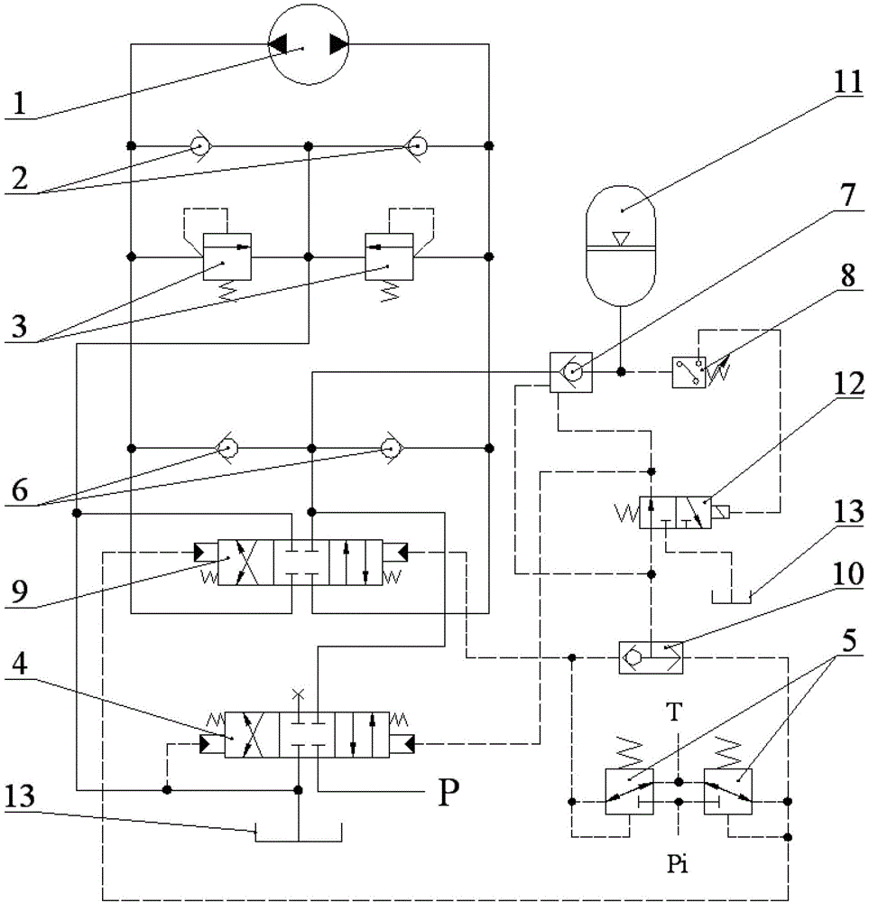
[0035] Such as image 3 shown. The excavator hydraulic rotary energy-saving system of the present invention includes a main control reversing valve 4, an overload oil supply valve group, a hydraulic motor 1, a pilot control valve group, and a fuel tank 13;

[0036] The overload oil supply valve group is composed of a first one-way valve group and an overload valve group, the first one-way valve group includes two one-way valves 2, and the overload valve group includes two overload valves 3;

[0037] The pilot control valve group includes two pilot valves 5;

[0038] The inlets of the two one-way valves 2 of the first one-way valve group are connected together with the outlets of the two overload valves 3, and then connected with the oil tank 13, and the outlets of the two one-way valves of the first one-way valve group The oil ports are respectively connected to the inlet and outlet main oil passages of the hydraulic motor 1; the oil inlets of the two overload valves 3 are r...


PUM


Abstract

The invention discloses a hydraulic swing energy-saving system for an excavator. A second one-way valve bank, a three-position four-way pilot operated reversing valve, a pilot operated one-way valve, a two-position three-way electromagnetic reversing valve, an energy accumulator, a shuttle valve and a pressure relay are additionally arranged on an existing hydraulic swing system; during braking, a motor is changed to a pump for pressing oil into the energy accumulator for storage by using the second one-way valve bank; the oil supply of the energy accumulator and the oil supply of a main pump by using a main control reversing valve are controlled by the three-position four-way pilot operated reversing valve; when the energy accumulator is at high liquid level, the pressure relay is on, the two-position three-way electromagnetic reversing valve is subjected to position change, a passage from a pilot valve to a liquid control port of the main control reversing valve is cut off, therefore the main control reversing valve is closed, and the energy accumulator supplies oil independently for driving the motor; when the energy accumulator reaches to the low liquid level, the pressure relay is off, the two-position three-way electromagnetic reversing valve is subjected to position return, an oil path from the pilot valve to the liquid control port of the main control reversing valve is connected, the main control reversing valve is open and replaces the energy accumulator for oil supply; thus brake energy can be recycled.

Description

technical field [0001] The invention relates to an excavator hydraulic system, in particular to an excavator hydraulic rotary energy-saving system. Background technique [0002] Such as figure 1 As shown, the excavator is mainly composed of an alighting part 1, a slewing device 2, an upper turntable 3 and a working device 4. The slewing device adopts hydraulic drive technology, the engine drives the hydraulic pump to provide hydraulic power, and drives the hydraulic slewing motor to drive the upper turntable 3 and working device 4 of the excavator to rotate through the reduction mechanism. During excavation operations, the slewing device is generally in a hydraulic braking state to ensure that the working device can perform effective excavation operations at a certain position. After digging and filling the bucket, it needs rotary motion to reach the unloading position to discharge the material. After the unloading is completed, it needs rotary motion to return to the digg...

Claims


Application Information

Patent Timeline
Patent Type & Authority Patents(China)
IPC IPC(8): E02F9/22
Inventor 迟永滨丁问司
Owner SOUTH CHINA UNIV OF TECH
Why Eureka
Try Eureka