Centrifugal fan and road sweeper

A technology of centrifugal fan and center of circle, applied in the field of sanitation, can solve the problems of reducing effective power utilization, large noise of centrifugal fan, pressure loss, etc., and achieve the effect of simple spatial structure layout, avoiding pressure loss and reducing noise.

Active Publication Date: 2013-12-04
ZOOMLION ENVIRONMENTAL IND CO LTD
View PDF7 Cites 6 Cited by
  • Summary
  • Abstract
  • Description
  • Claims
  • Application Information

AI Technical Summary

Problems solved by technology

[0002] Existing centrifugal fans are generally figure 1 In the form shown, the air inlet 6 is arranged on the volute 1 along the axial direction of the centrifugal fan, and the air outlet 7 is arranged tangentially to the volute 1 in a direction parallel to the front and rear disks of the volute. Therefore, For the existing centrifugal fans, the air inlet direction and the air outlet direction are vertical, but when the centrifugal fan is used on some specific equipment, this may cause inconvenience, for example, on a road sweeper, the air inlet duct Bot

Method used


Image

  • Centrifugal fan and road sweeper
  • Centrifugal fan and road sweeper
  • Centrifugal fan and road sweeper

Examples


Embodiment Construction

[0024] Specific embodiments of the present invention will be described in detail below in conjunction with the accompanying drawings. It should be understood that the specific embodiments described here are only used to illustrate and explain the present invention, and are not intended to limit the present invention.

[0025] In the present invention, in the case of no contrary description, the used orientation words such as "vertical, horizontal" are consistent with the directions shown in the accompanying drawings; outside.

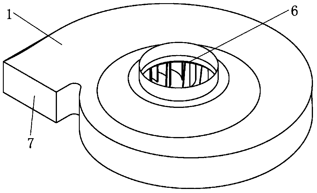
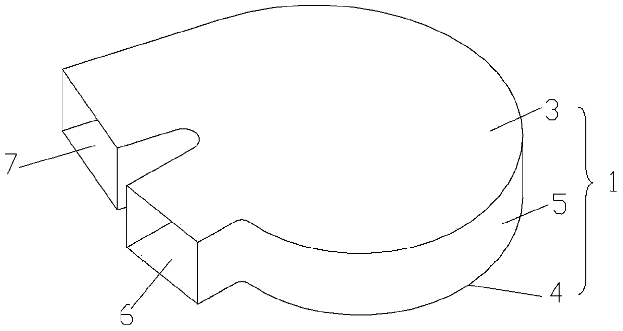
[0026] The present invention provides a centrifugal fan, which comprises a volute 1 and an impeller 2 arranged in the volute 1, the volute 1 comprises an air inlet 6, an air outlet 7, a front disc 3 arranged in parallel and an The rear plate 4 and the connecting portion 5 arranged between the front plate 3 and the rear plate 4, the air inlet 6 and the air outlet 7 are all along the front plate 3 and the rear plate 4 Parallel directions are provided on...


PUM


Abstract

The invention discloses a centrifugal fan and a road sweeper. The centrifugal fan comprises a volute and an impeller arranged in the volute. The volute comprises an air inlet, an air outlet, a front disk, a rear disk and a connecting part, wherein the front disk and the rear disk are arranged in parallel; the connecting part is arranged between the front disk and the rear disk; and both the air inlet and the air outlet are formed on the connecting part along the parallel direction of the front disk and the rear disk. The road sweeper comprises the centrifugal fan. When the centrifugal fan disclosed by the invention is applied to a certain specific equipment, for example, when the centrifugal fan is used in the road sweeper of which an air inlet pipeline and an air outlet pipeline are both in parallel to the front disk and the rear disk of the volute, a reversing elbow does not need to be specially arranged to reverse airflow in the volute and the airflow can directly enter the volute from the air inlet through the air inlet pipeline without being reversed, and thus, the space structural layout is simplified, pressure loss is avoided and noise is also reduced.

Description

technical field [0001] The invention relates to the field of sanitation, in particular to a centrifugal fan and a road sweeper equipped with the centrifugal fan. Background technique [0002] Existing centrifugal fans are generally figure 1 In the form shown, the air inlet 6 is arranged on the volute 1 along the axial direction of the centrifugal fan, and the air outlet 7 is arranged tangentially to the volute 1 in a direction parallel to the front and rear disks of the volute. Therefore, For the existing centrifugal fans, the air inlet direction and the air outlet direction are vertical, but when the centrifugal fan is used on some specific equipment, this may cause inconvenience, for example, on a road sweeper, the air inlet duct Both the air inlet pipe and the air outlet pipe are set parallel to the front and rear disks of the volute, but since the air inlet 6 is arranged along the axial direction of the volute 1, it is necessary to connect the air inlet pipe to the air ...

Claims


Application Information

Patent Timeline
IPC IPC(8): F04D29/42
Inventor 张斌彭林斌张劲肖庆麟龙亮
Owner ZOOMLION ENVIRONMENTAL IND CO LTD
Why Eureka
Try Eureka