Light emitting diode module

A technology of light-emitting diodes and light-emitting elements, which is applied in the direction of light source, electric light source, light source fixing, etc., can solve the problems of inability to control the reflection angle of the light-emitting diode chip, poor thermal conductivity of the insulating layer, etc., and achieve the effect of easy positioning.

Inactive Publication Date: 2013-12-04
ELEMENTECH INT
View PDF5 Cites 4 Cited by
  • Summary
  • Abstract
  • Description
  • Claims
  • Application Information

AI Technical Summary

Problems solved by technology

However, since the aluminum substrate is covered with an insulating layer and a circuit layer in sequence, the circuit layer and the aluminum substrate are electrically insulated by the insulating layer, and the thermal conductivity of the insulating layer is poor, which will reduce the overall heat dissipation effect.
The ceramic substrate is not easy to process to make grooves and other structures, so that the grooves cannot be used to fix the fluorescent glue or sealant, and the grooves cannot be used to control the reflection angle of the light emitted by the LED chip to achieve the desired light emission. angle
[0005] In addition, most of the existing light-emitting diode bulbs set the driving circuit in the lamp holder, and then connect the driving circuit with wires passing through the lamp holder. Usually, the size and weight of the driving circuit are relatively large, and the lamp holder needs to reserve a considerable internal space to accommodate drive circuit

Method used


Image

  • Light emitting diode module
  • Light emitting diode module
  • Light emitting diode module

Examples


Embodiment Construction

[0030] Relevant technical content and detailed description of the present invention, cooperate accompanying drawing to illustrate as follows:

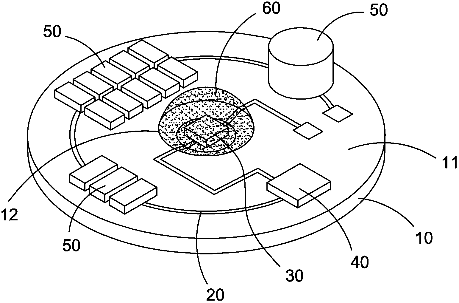
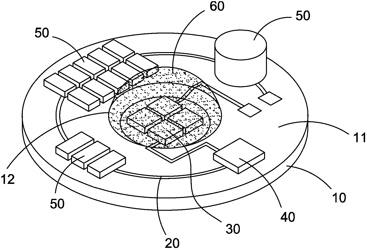
[0031] Such as figure 1 As shown, the LED module according to an embodiment of the present invention includes a ceramic substrate 10 , a circuit layer 20 , a light emitting element 30 , a driving circuit element 40 , and a plurality of electronic elements 50 .

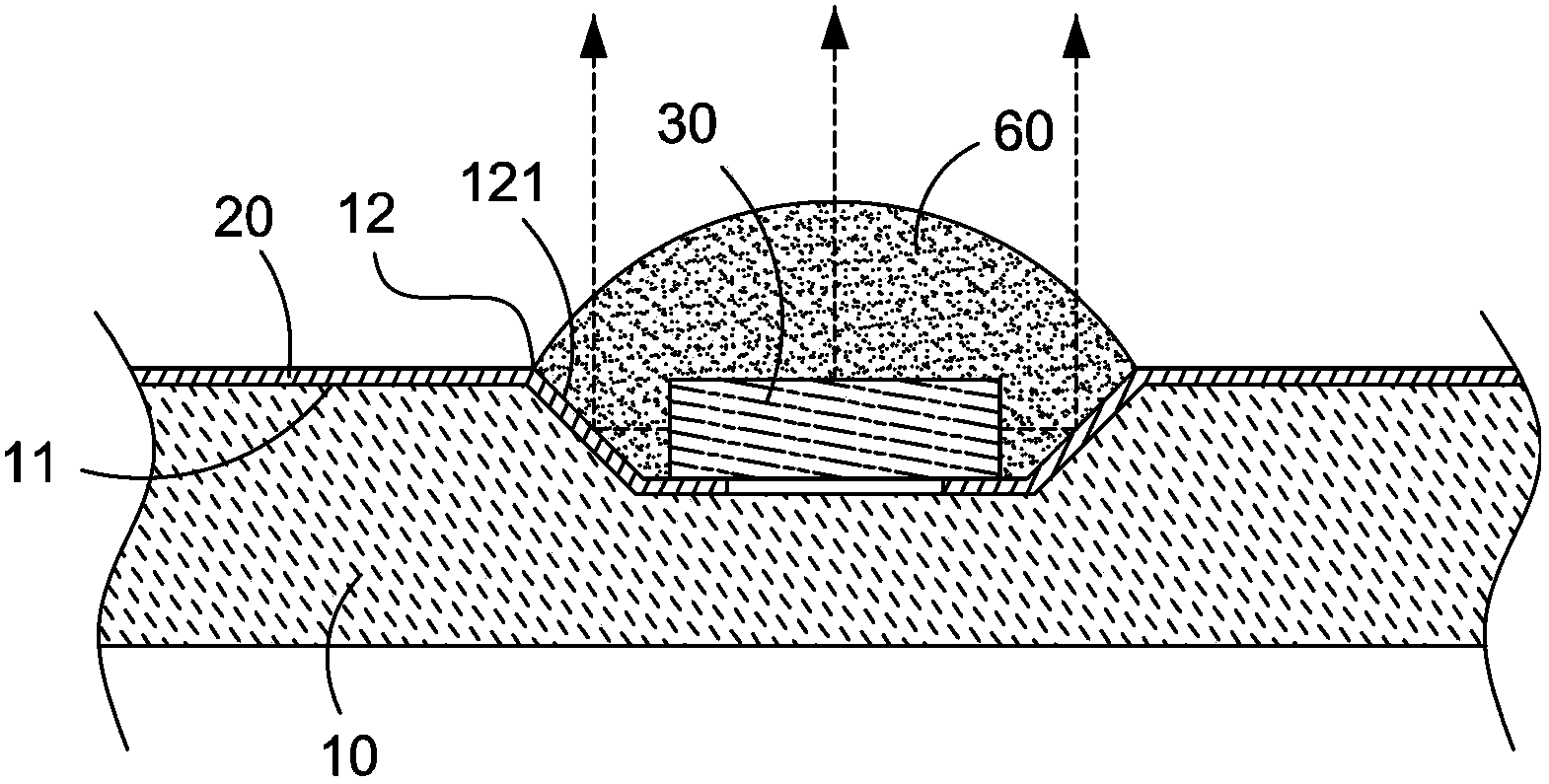
[0032] The ceramic substrate 10 has a groove 12 on the upper surface 11 thereof. The ceramic substrate 10 is formed by sintering ceramic powder. Through appropriate mold matching, the ceramic substrate 10 has the groove 12 when it is formed, without using other subsequent processing methods to make the groove on the general flat ceramic material, which can avoid the difficulty of processing the high-hardness ceramic substrate. difficulty.

[0033] The circuit layer 20 is located on the upper surface 11 of the ceramic substrate 10 . The circuit layer 20 is made of copper or ...


PUM


Abstract

The invention discloses a light emitting diode module which comprises a ceramic substrate, a circuit layer, at least one light emitting element and a driving circuit element. The ceramic substrate is provided with a groove formed in the upper surface of the ceramic substrate, the circuit layer is arranged on the upper surface of the ceramic substrate, the light emitting element is arranged in the groove and electrically connected with the circuit layer, and the driving circuit element is arranged on the upper surface of the ceramic substrate and electrically connected with the circuit layer. Due to the fact that the ceramic substrate provided with the groove when formed is provided, the difficulty that the high-hardness ceramic substrate is hard to machine can be effectively avoided. Due to the fact that sealing glue is contained in the groove, the sealing glue is easily positioned and forms a lens shape.

Description

technical field [0001] The invention relates to a light emitting module, in particular to a light emitting module using a light emitting diode as a light source. Background technique [0002] Due to the advantages of energy saving, LEDs are gradually playing an important role in the field of lighting. In order to replace energy-consuming incandescent lamps, light-emitting diode bulbs must adopt a simpler structure or process in order to reduce the manufacturing cost to a level acceptable to consumers. [0003] Today's LED light bulbs have begun to adopt the method of chip direct packaging (Chip on Board), directly fixing the LED chip on the circuit board, abandoning the existing pre-packaged LED chip, and then installing the packaged LED components on the circuit board on the way. [0004] In addition, in order to quickly dissipate the heat generated by the LED chips during operation, most commonly used circuit boards use aluminum substrates or ceramic substrates to help d...

Claims


Application Information

Patent Timeline
Patent Type & Authority Applications(China)
IPC IPC(8): F21S2/00F21V19/00F21V23/00F21Y101/02
Inventor 忻鼎国
Owner ELEMENTECH INT
Why Eureka
Try Eureka