Vacuum precise displacement device

A precision displacement and vacuum technology, applied in the field of vacuum instruments, can solve the problems that the displacement device cannot be installed, the instrument or device cannot be installed, etc., and achieves the effect of saving the installation area, compact structure and improving mechanical properties.

Active Publication Date: 2013-12-04
INST OF PHYSICS - CHINESE ACAD OF SCI
View PDF7 Cites 1 Cited by
  • Summary
  • Abstract
  • Description
  • Claims
  • Application Information

AI Technical Summary

Problems solved by technology

If the installation takes up too much space, the displacement device may not be able to be installed on the vacuum chamber, or other instruments or devices may not be installed, which will cause great inconvenience to the production or experiment using vacuum

Method used


Image

  • Vacuum precise displacement device
  • Vacuum precise displacement device

Examples


Embodiment Construction

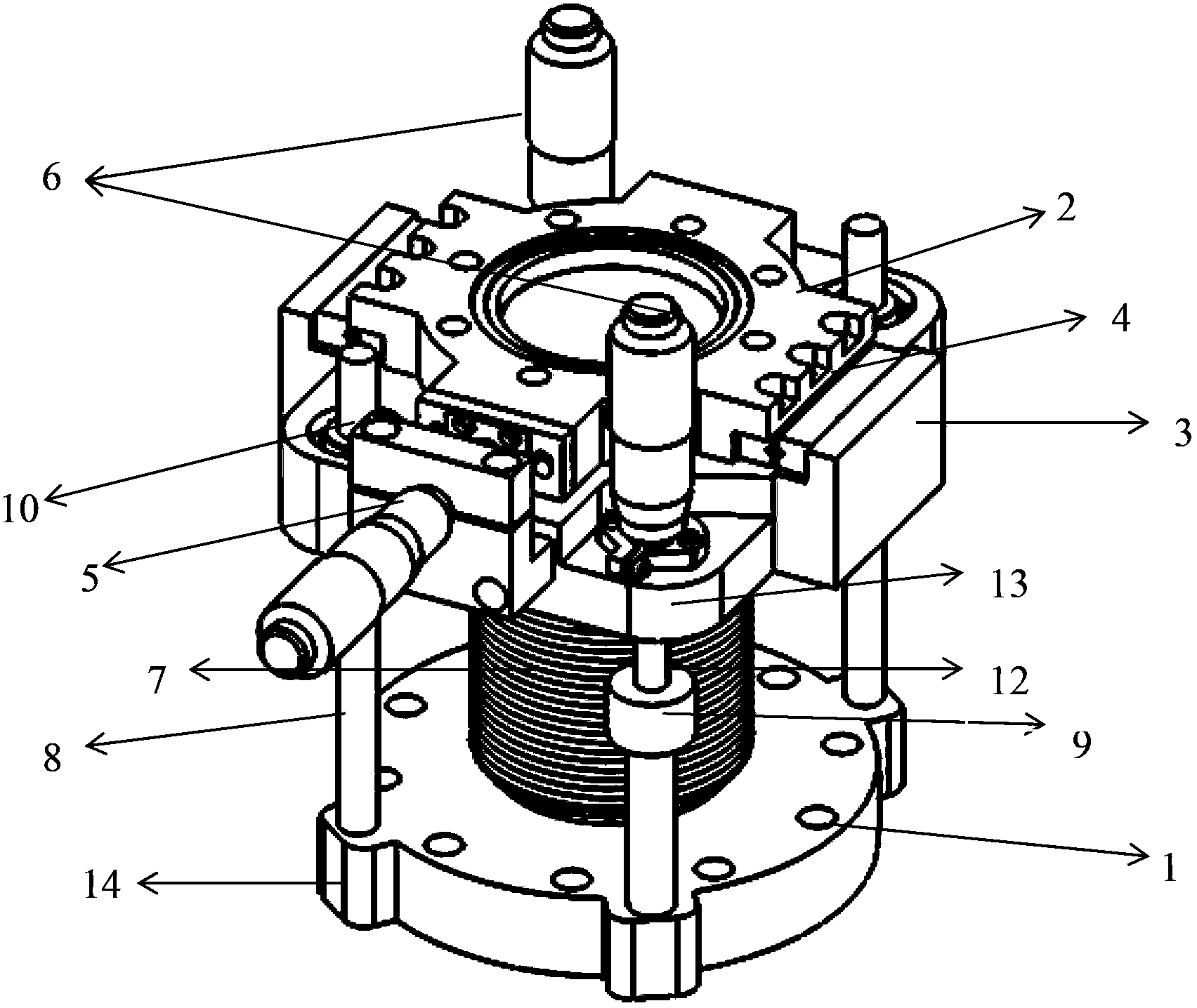
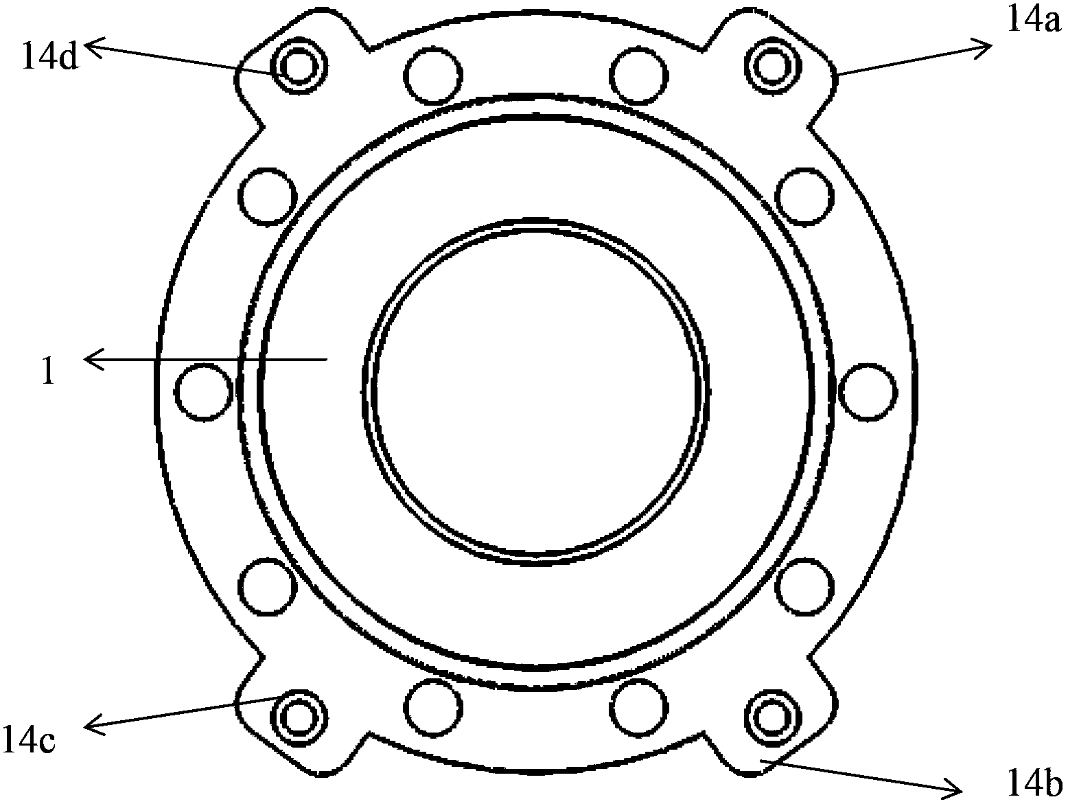
[0020] The present invention generally provides a vacuum precision displacement device, including: a bottom flange 1 installed on the vacuum chamber; a top flange 2; a bellows 7 connecting the bottom flange 1 and the top flange 2, and the axis of the bellows 7 The direction is defined as the longitudinal direction; it is used to install the displacement platform 3 of the top flange 2, and the top flange 2 can move in translation relative to the displacement platform 3; it is used to drive the motion mechanism of the top flange 2 to move. The motion mechanism includes a first motion device 5 and a second motion device 6. The first motion device 5 can make the top flange 2 move in translation relative to the displacement table 3, and the second motion device 6 can make the displacement table 3 move longitudinally relative to the bottom flange 1. sports. Wherein, the second moving device 6 connects the bottom flange 1 and the translation stage 3 . The vacuum precision displaceme...


PUM


Abstract

The invention provides a vacuum precise displacement device. The displacement device comprises a bottom flange (1), a top flange (2), a corrugated pipe (7) through which the two flanges are connected, a displacement platform (3) used for installation of the top flange (2) and relative to which the top flange (2) can move translationally, and a moving mechanism used to drive the top flange (2) and comprising a first moving device (5) and second moving devices (6). Through the first moving device (5), the top flange (2) can move translationally relative to the displacement platform (3). Through the second moving devices (6), the displacement platform (3) can move longitudinally relative to the bottom flange (1). The displacement device comprises at least two second moving devices (6) which are connected with the bottom flange (1) and the displacement platform (3). The second moving devices (6) are arranged on the bottom flange (1) in a roughly evenly-spaced way, and move the displacement platform (3) as well as support the displacement platform (3). The displacement device has advantages of simple structure, small occupied area, low cost and good mechanical properties.

Description

technical field [0001] The invention relates to a vacuum instrument, in particular to a vacuum precision displacement device. Background technique [0002] In scientific research and industrial production in some special fields, sometimes in order to ensure the purity of materials and eliminate external interference, people need to carry out material preparation or scientific experiments in a vacuum environment. This vacuum condition is usually achieved and maintained using a vacuum chamber and a set of vacuum pumps. Inside the vacuum chamber, the sample is usually mounted on a dedicated sample stage. With the help of this sample stage, people can clean the surface of the sample by ion sputtering and high-temperature annealing, and can also use the evaporation source to evaporate the sample. At the same time, in order to perform different tests, the samples also need to be transferred in different chambers. These operations require precise alignment of the sample and prec...

Claims


Application Information

Patent Timeline
Patent Type & Authority Applications(China)
IPC IPC(8): G01N1/36
Inventor 郭晓东谢楠颜世超宫会期单欣岩郭阳陆兴华
Owner INST OF PHYSICS - CHINESE ACAD OF SCI
Why Eureka
Try Eureka