Sealed N2 cleaning device

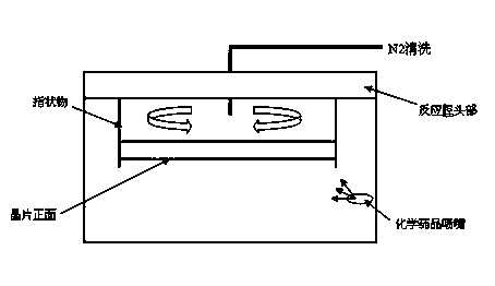
A cleaning device and sealing ring technology, which is applied in electrical components, semiconductor/solid-state device manufacturing, circuits, etc., can solve the problems of N2 cleaning adapter 102 leakage, wafer backside contamination, etc., and achieve the effect of improving sealing conditions and avoiding chemical pollution.

Inactive Publication Date: 2013-12-04
SHANGHAI HUAHONG GRACE SEMICON MFG CORP
View PDF5 Cites 2 Cited by
  • Summary
  • Abstract
  • Description
  • Claims
  • Application Information

AI Technical Summary

Problems solved by technology

like figure 2 As shown, the N2 cleaning device includes an N2 cleaning tube 101 and an N2 cleaning adapter 102. The N2 cleaning tube 101 is in direct contact with the N2

Method used


Image

  • Sealed N2 cleaning device
  • Sealed N2 cleaning device
  • Sealed N2 cleaning device

Examples


Example Embodiment

[0011] based on the following image 3 Preferred embodiments of the present invention will be described in detail.

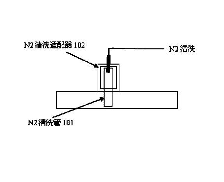
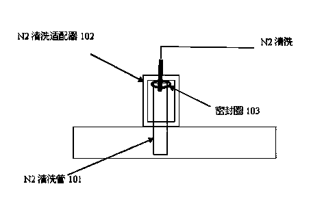
[0012] like image 3 As shown, the present invention provides a sealed N2 cleaning device, which includes an N2 cleaning tube 101 and an N2 cleaning adapter 102, and also includes a sealing ring 103 arranged on the contact surface of the N2 cleaning tube 101 and the N2 cleaning adapter 102;

[0013] The sealing ring 103 is an O-ring;

[0014] The O-shaped sealing ring is fluororubber or silicon fluororubber which can resist corrosion and provide airtight function.

[0015] Although the content of the present invention has been described in detail through the above preferred embodiments, it should be understood that the above description should not be considered as limiting the present invention. Various modifications and alterations to the present invention will become apparent to those skilled in the art upon reading the above disclosure. Therefore, the pro...


PUM


Abstract

The invention discloses a sealed N2 cleaning device. The sealed N2 cleaning device comprises an N2 cleaning tube and an N2 cleaning adaptor, and further comprises a sealing ring arranged between the contact surfaces of the N2 cleaning tube and the N2 cleaning adaptor. The sealed N2 cleaning device improves sealing conditions and prevents the back side of a wafer from chemical pollution.

Description

technical field [0001] The invention relates to a sealed N2 cleaning device. Background technique [0002] like figure 1 As mentioned above, in the semiconductor manufacturing process, when the front of the wafer is cleaned with chemicals in the reaction chamber, the wafer is fixed by fingers, and chemicals are sprayed from the chemical nozzle to clean the front of the wafer. In order to prevent the back of the wafer from being cleaned by chemicals Sputtering, use N2 cleaning device to protect the back of the wafer, pass the N2 cleaning device through the head of the reaction chamber, and N2 cleaning flow flows on the back of the wafer to prevent the back of the wafer from being chemically polluted. like figure 2 As shown, the N2 cleaning device includes an N2 cleaning tube 101 and an N2 cleaning adapter 102. The N2 cleaning tube 101 is in direct contact with the N2 cleaning adapter 102. The N2 cleaning adapter 102 is prone to leakage. If the intensity of the N2 cleaning ...

Claims


Application Information

Patent Timeline
IPC IPC(8): H01L21/67
Inventor 华良包中诚陈超华俊杰
Owner SHANGHAI HUAHONG GRACE SEMICON MFG CORP
Why Eureka
Try Eureka