Piezoelectric Linear Motor Driven by Bipeds and Electric Excitation Method

A linear motor and piezoelectric technology, applied in the direction of generators/motors, piezoelectric effect/electrostrictive or magnetostrictive motors, electrical components, etc., can solve the problem that the clamping unit cannot be clamped and the parallelism of the guide rails is difficult , reduce the efficiency of movers and other issues, and achieve the effects of easy mass production, improved service life and improved motor efficiency

Inactive Publication Date: 2016-01-13
NANJING UNIV OF AERONAUTICS & ASTRONAUTICS
View PDF3 Cites 0 Cited by
  • Summary
  • Abstract
  • Description
  • Claims
  • Application Information

AI Technical Summary

Problems solved by technology

[0006] First, the key to the stepping of the inchworm-type clamping piezoelectric motor is that the two clamping units can alternately lock the parallel guide rails, and the two clamping units are separated by a certain distance in the direction of motion, which requires parallel guide rails The parallelism must be high enough. Under the existing technical conditions, it is very difficult to achieve a high parallelism between the two guide rails with a long distance, which requires high production costs.
[0007] Second, the parallel guide rails of the inchworm clamp stepping piezoelectric motor are fixed, and the wear at both ends of the clamp unit will eventually lead to the inability to achieve clamping, resulting in failure
[0008] Third, laminated piezoelectric ceramics can only withstand a small pulling force, but can withstand a large thrust. Therefore, when the drive unit is shortened, the working ability of the laminated piezoelectric ceramics is very small, which reduces the movement of the mover. s efficiency
[0009] Fourth, when all the laminated piezoelectric ceramics are powered off, the locking force between the clamping unit and the parallel guide rail is much smaller than that of the clamping unit locking the parallel guide rail, so the inchworm-type clamping step Piezoelectric motors have almost no power-off self-locking ability

Method used


Image

  • Piezoelectric Linear Motor Driven by Bipeds and Electric Excitation Method
  • Piezoelectric Linear Motor Driven by Bipeds and Electric Excitation Method
  • Piezoelectric Linear Motor Driven by Bipeds and Electric Excitation Method

Examples


Embodiment Construction

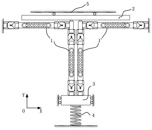
[0032] Please refer to Figure 1 to Figure 3 As shown, the biped driven piezoelectric linear motor of the present invention is composed of a first stator group 1, a second stator group 1', a mover / linear guide rail 2, a preload guide rail 3, a preload spring 4 and a base 5. Among them, the first stator group 1 and the second stator group 1' of the piezoelectric linear motor are symmetrically distributed along the axis, and one end is fixedly connected to the preloaded guide rail 3, and the other end is fixedly connected to the base 5; Under the action of the elastic restoring force, the first stator group 1 and the second stator group 1' keep in contact with the mover / linear guide rail 2, so that the piezoelectric linear motor has a power-off self-locking function.

[0033]The first stator group 1 and the second stator group 1' are placed side by side and symmetrical along the Y axis. The first stator group 1 and the second stator group 1' are pressed on the mover / linear guide...


PUM


Abstract

The invention discloses a double-foot driving piezoelectric linear motor and an electric excitation mode. The motor is composed of two stator sets, a rotor / linear guide rail, a pre-pressing guide rail, a pre-pressing spring and a base. The two stator sets are distributed symmetrically along axes, and the ends of the two stator sets are fixedly connected with the pre-pressing guide rail. Under the action of elastic restoring force generated by elastic deformation of the pre-pressing spring, the two stator sets keep in contact with the rotor / linear guide rail, so that an outage self-locking function is provided for the piezoelectric linear motor. Each of the two stator sets is composed of piezoelectric actuation units, flexible connectors and a driving foot, wherein two ends of the piezoelectric actuation units are connected with the driving feet and the base through the flexible connectors. The piezoelectric actuation units serve as modular structures, so that the whole motor structure is simple, the motor assembly efficiency is improved, and batch production is facilitated. According to the double-foot driving piezoelectric linear motor and the electric excitation mode, the rotor / linear guide rail can be driven by the two stator sets alternately to perform rectilinear motion by imposing specific excitation voltage signals on laminated piezoelectric ceramic sets in the piezoelectric actuation units.

Description

Technical field: [0001] The invention relates to a biped-driven piezoelectric linear motor and an electric excitation method, belonging to the technical field of piezoelectric precision actuation. Background technique: [0002] In recent years, with the rapid development of high-tech fields such as integrated circuit manufacturing, biomedicine, precision manufacturing, and optoelectronics / optical fiber industry, there is an urgent need for micro- and nanoscale drivers. However, due to factors such as low efficiency during miniaturization, low positioning accuracy, and complex structure, the traditional electromagnetic driver cannot fully meet the requirements. So countries around the world began to explore and develop various new drivers that can meet the above requirements. [0003] The inverse piezoelectric effect of piezoelectric ceramics can convert electrical energy into mechanical energy. The piezoelectric linear motor designed based on this effect converts the micron...

Claims


Application Information

Patent Timeline
Patent Type & Authority Patents(China)
IPC IPC(8): H02N2/02H02N2/04H02N2/06
Inventor 王寅黄卫清李海林
Owner NANJING UNIV OF AERONAUTICS & ASTRONAUTICS
Why Eureka
Try Eureka