Acceleration and deceleration control device

An acceleration and deceleration control, acceleration and deceleration technology, applied in the direction of the deceleration device of the AC motor, the electric motor/converter plug, etc., can solve the problems that the motor cannot be completely stopped, the deceleration time is short, the actual speed does not follow, etc., and shorten the DC control. The effect of moving time

Inactive Publication Date: 2016-08-03
MITSUBISHI ELECTRIC CORP
View PDF7 Cites 0 Cited by
  • Summary
  • Abstract
  • Description
  • Claims
  • Application Information

AI Technical Summary

Problems solved by technology

[0003] At this time, for the case where the output frequency of the converter becomes zero frequency, sometimes if the inertia including the motor and its load is large and the deceleration time is short, the actual speed of the motor does not follow the output frequency of the converter. Even after the output of the converter is cut off, the motor does not come to a complete stop and rotates in a free running state

Method used


Image

  • Acceleration and deceleration control device
  • Acceleration and deceleration control device
  • Acceleration and deceleration control device

Examples


Embodiment approach 1

[0026] Before describing the variable speed control device 100 according to Embodiment 1, using Figure 9 , the variable speed control device 1 according to the basic form will be described.

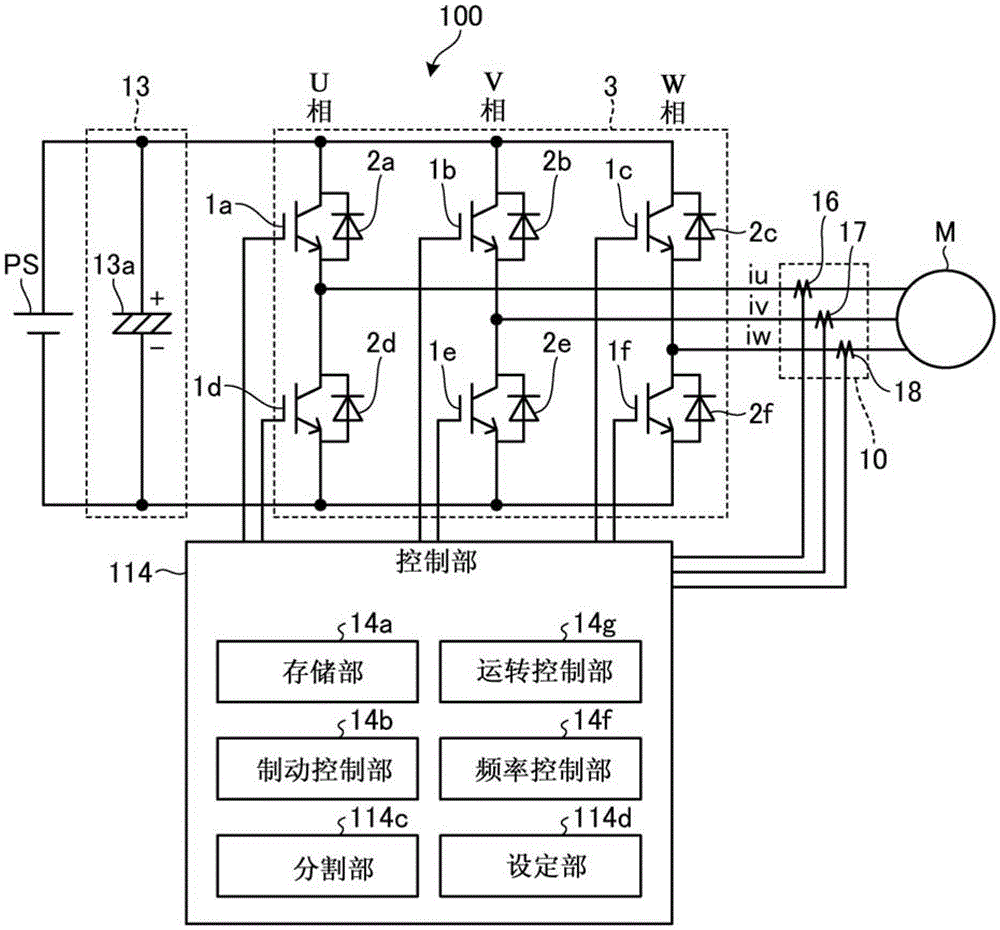
[0027] The variable speed control device 1 drives a motor M using a semiconductor power converter 3 . That is, the variable speed control device 1 converts DC power into AC power by the semiconductor power converter 3 based on the control by the control unit 14 , and supplies the converted AC power to the motor M, thereby driving the motor M.

[0028] Specifically, the variable speed control device 1 includes a smoothing unit 13 , a semiconductor power converter (drive unit) 3 , a current detection unit 10 , and a control unit 14 .

[0029] Smoothing unit 13 receives DC power from DC power supply PS. The smoothing unit 13 includes, for example, a smoothing capacitor 13 a , smoothes the DC power using the smoothing capacitor 13 a , and supplies the smoothed DC power to the semiconductor...

Embodiment approach 2

[0075] Next, use Figure 5 , the acceleration / deceleration control device 200 according to Embodiment 2 will be described. Figure 5 It is a figure which shows the structure of the acceleration-deceleration control apparatus 200. Hereinafter, description will be given centering on parts different from the basic method.

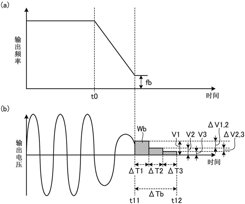
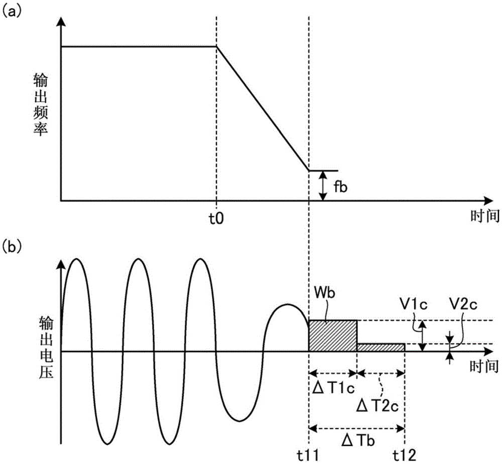
[0076] In Embodiment 1, the DC braking voltage is decreased in steps, for example, according to the elapsed time from the start timing of the DC braking time, but in Embodiment 2, the DC braking voltage is decreased corresponding to the time from the start timing of the DC braking time. The elapsed time is calculated so that the DC braking voltage decreases in a functional manner.

[0077] Specifically, as Figure 5 As shown, in the acceleration and deceleration control device 200, instead of the control unit 14 (refer to Figure 9 ) and has a control unit 214 . The control unit 214 has a setting unit (first setting unit) 214e and a setting unit (second s...


PUM


Abstract

PROBLEM TO BE SOLVED: To obtain an acceleration deceleration controller capable of stopping a motor smoothly at a target stop position in a short time.SOLUTION: The acceleration deceleration controller for accelerating and decelerating a motor includes a drive unit for driving the motor, and a control unit for controlling the drive unit so as to perform DC braking when stopping the motor. The control unit includes a division unit for diving a DC braking time into N (an integer of 2 or more) periods, a setting unit for setting the DC braking voltage so that the amplitude of the last period is smallest for the N periods thus divided, respectively, and a brake control unit for controlling the drive unit so as to perform DC braking according to the DC braking voltage of the N periods thus set.

Description

technical field [0001] The invention relates to an acceleration and deceleration control device. Background technique [0002] In a device that uses a semiconductor power converter to drive a motor, the acceleration / deceleration control of the motor is achieved by controlling the output frequency of the converter and then controlling the output voltage. Among them, as the deceleration control method, it is a method of gradually reducing the output frequency of the converter from the current frequency to zero frequency. [0003] At this time, for the case where the output frequency of the converter becomes zero frequency, sometimes if the inertia including the motor and its load is large and the deceleration time is short, the actual speed of the motor does not follow the output frequency of the converter. Even after the output of the converter is cut off, the motor does not come to a complete stop and rotates in a free running state. [0004] As a countermeasure, there is ...

Claims


Application Information

Patent Timeline
Patent Type & Authority Patents(China)
IPC IPC(8): H02P3/24
Inventor 道祖尾龙太寺岛觉
Owner MITSUBISHI ELECTRIC CORP
Why Eureka
Try Eureka