
Method for manufacturing long rotor punch of magnetic suspension linear motor and special die

A technology of a linear motor and a manufacturing method, applied in the field of mold sets, can solve the problems of complex structure of composite molds, poor reliability, long stroke of top block, etc., to reduce equipment costs and mold opening costs, high reliability and strong versatility. Effect

Active Publication Date: 2015-03-18
NEW UNITED GROUP
View PDF6 Cites 0 Cited by
  • Summary
  • Abstract
  • Description
  • Claims
  • Application Information

AI Technical Summary

Problems solved by technology

However, there are the following defects: (1) The size of the workpiece is huge, and a large-tonnage punching machine with a large work table is required for one-time molding processing; (2) The composite mold required for processing is complex in structure and huge in size, which makes it difficult to manufacture and assemble; if the integral type is used The concave mold needs to be made by a large wire cutting machine tool, and the concave mold is easily deformed and scrapped during the processing process, and heat treatment is difficult; if the concave mold with a segmented structure is used, the complexity of the mold structure will be increased, and a large number of convex molds only need to have If a failure occurs, the mold must be stopped for repair, and the reliability is poor; (3) If the groove distance, groove shape, tie rod hole distance, etc. are adjusted, the entire mold can only be scrapped
[0004] If the progressive die processing method is adopted to process 29 grooves and 5 tie rod holes in four times each time, because the punch head of the long mover, the distance between the tail grooves and the distance between the tie rod holes are not equally divided, two more pairs of molds are required The two ends of the punching sheet after the die processing are processed, and the dimensional accuracy is seriously affected after the workpiece is positioned multiple times, and the work efficiency of multiple positioning is low
Moreover, when the groove distance, groove shape, tie rod hole distance, etc. are adjusted, the whole set of 3 molds can only be scrapped
Due to the large size and complex structure of the progressive die to be used, the cost of this solution is relatively high
[0005] If wire-cut machine tools are used for processing, even if 200 pieces are stacked each time, the processing time and cost will be huge, and the dimensional accuracy of the parts cannot be guaranteed, and industrialized large-scale production cannot be carried out.
[0006] After searching, the Chinese patent document with the publication number CN103071731A discloses a pneumatic exchange stamping die. A jack block driven by a horizontal cylinder is installed between the punch and the upper plate, and the position of the jack block is used to switch a certain punch to work / In the non-working state, different punches can be switched on a set of molds to achieve stamping of different shapes, but the stroke of the jack block is long, and the installation position of the punch is also limited by the size of the jack block and the cylinder, resulting in the entire set of molds The volume is large, and the top block must be inserted between the punch and the upper plate after the punch is completely reset by the spring, and the switching reliability is insufficient.

Method used


Image

  • Method for manufacturing long rotor punch of magnetic suspension linear motor and special die
  • Method for manufacturing long rotor punch of magnetic suspension linear motor and special die
  • Method for manufacturing long rotor punch of magnetic suspension linear motor and special die

Examples


Embodiment

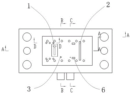
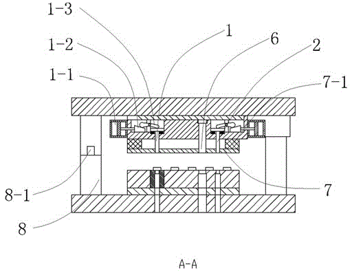
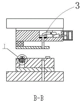
[0029] Embodiment: The special mold for punching the long mover of the magnetic levitation linear motor in this embodiment is as follows Figure 1 to Figure 6 As shown, including upper and lower templates. The first punch 1 for punching grooves, the second punch 2 for cutting, the third punch 3 for punching tie rod holes and the first punch for punching semicircular mark grooves are installed on the upper template. Four punches 4, and a pilot hole punch 5, a pilot pin 5-1, and a trimming punch 6. Among them, the first punch 1, the second punch 2, the third punch 3, and the fourth punch 4 are independent of each other, and all include a working part that can extend out of the upper template and a tail embedded in the upper template, and the tail is against the corresponding One end of the lever, and the other end of the lever rests on the slope of the wedge driven by the corresponding horizontal cylinder. Taking the first punch 1 as an example, its tail abuts against one end ...


PUM


Abstract

The invention discloses a method for manufacturing a long rotor punch of a magnetic suspension linear motor and a special die. The manufacturing method mainly comprises the steps of arranging special equipment, inputting a relationship between dimension parameters and step pitch into a programmable logic controller, controlling a controllable male die in the punching process and the like. The special die mainly comprises a controllable male die formed by a cylinder, a tapered wedge, a lever and a male die. The manufacturing method has the advantages of low processing cost and high efficiency, and the special die is compact in structure and high in reliability.

Description

technical field [0001] The invention relates to a mold set and a manufacturing method using the mold set, in particular to a manufacturing method and a special mold for a long mover of a magnetic levitation linear motor. Background technique [0002] The long mover punching piece of the magnetic levitation linear motor has a special structure, one side of which is uniformly distributed with slots at equal distances, but the tie rod holes on the other side have unequal hole spacing, and the end has a semicircular marking groove , the tail groove pitch is not equal, and the existing processing methods all have their own defects: [0003] The processing method of punching the long mover piece by one stamping with the compound mold has the advantage that it is not affected by the feeding accuracy and the precision of the workpiece is high. However, there are the following defects: (1) The size of the workpiece is huge, and a large-tonnage punching machine with a large work tabl...

Claims


Application Information

Patent Timeline
Patent Type & Authority Patents(China)
IPC IPC(8): B21D35/00B21D37/10
Inventor 潘宏兴冯建兴朱宁
Owner NEW UNITED GROUP
Learn More