Compression roller drive mechanism of flying saw machine

A transmission mechanism, the technology of flying saw machine, which is applied to the attachment of sawing machine, sawing machine device, metal sawing equipment, etc. And other issues

Inactive Publication Date: 2013-12-11
江苏省南扬机械制造有限公司
View PDF8 Cites 0 Cited by
  • Summary
  • Abstract
  • Description
  • Claims
  • Application Information

AI Technical Summary

Problems solved by technology

Its disadvantages are: when the sports car is moving in a straight line, it is affected by external forces, and may jump on the guide rail, which affects the meshing transmission of the rack and pinion, and at the same time causes the wear and tear of the rack and pinion to increase; in addition, the gap between the gear and the rack There is a large gap, which will also affect the cutting accuracy of the flying saw machine

Method used


Image

  • Compression roller drive mechanism of flying saw machine
  • Compression roller drive mechanism of flying saw machine

Examples


Embodiment Construction

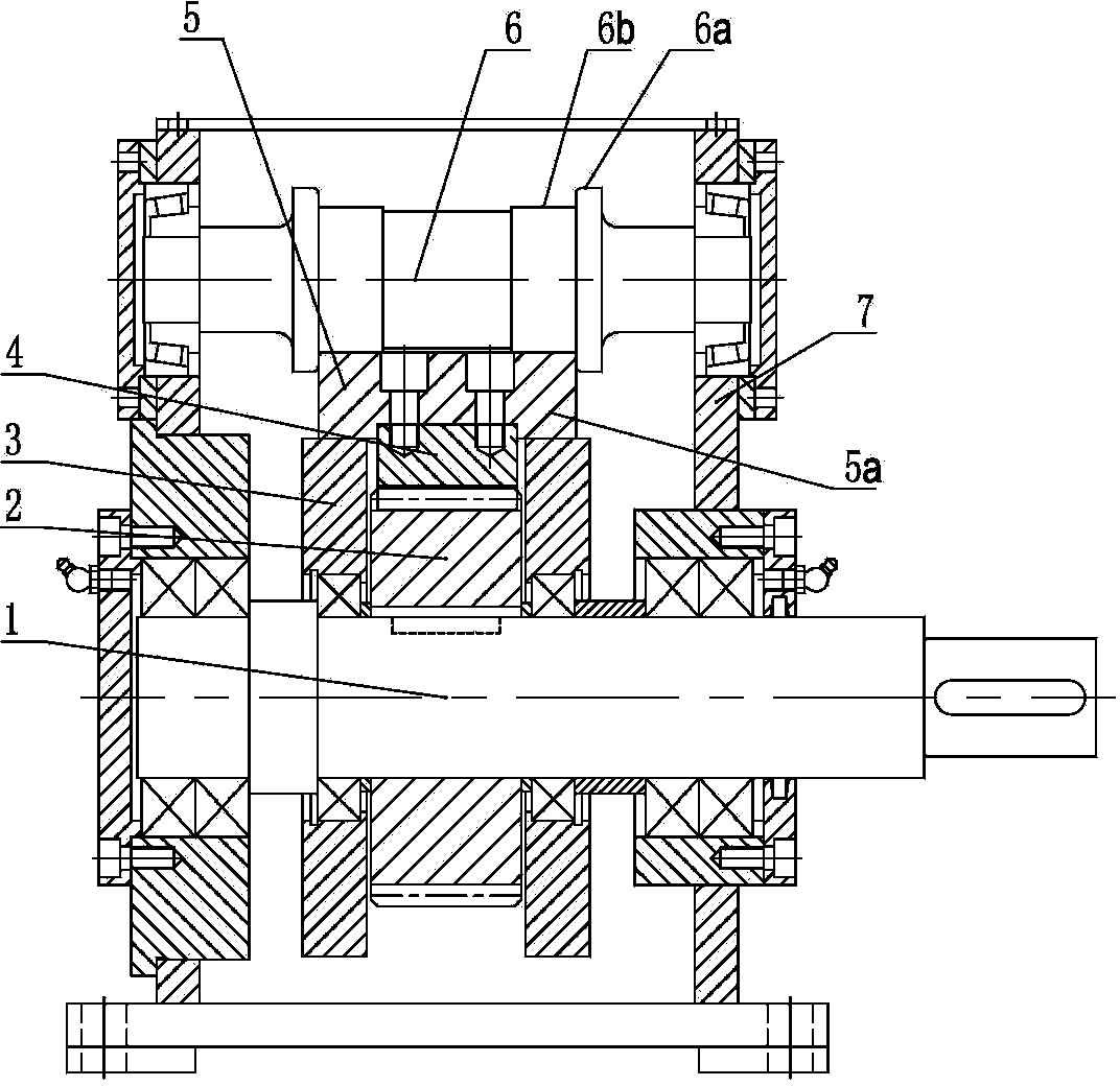
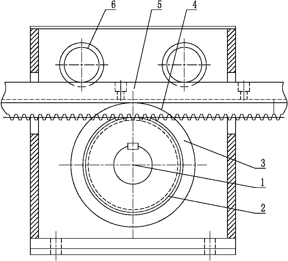
[0012] Such as Figure 1-2 As shown, it is a pressure roller transmission mechanism of a flying saw machine, which includes a gear 2 and a rack 4 that mesh with each other. The gear 2 is installed on the gear shaft 1, and the end of the gear shaft 1 is connected to the servo motor. The rack 4 and the The sports car of the flying saw machine is relatively fixed. When the rack 4 moves linearly, it can drive the sports car to move linearly. The device includes a frame 7, and the gear shaft 1 is rotatably arranged on the frame 7 through the bearing and the bearing seat. The gear shaft 1 is located on both sides of the gear 2 and is respectively rotatably provided with idlers 3, the idlers 3 can rotate relative to the gear shaft 1, and the two are supported and connected by bearings; the rack 4 is installed on the lower side of the rack seat 5, and the gear Both sides of the bar seat 5 are respectively provided with protruding parts 5a protruding from both sides of the rack, and th...


PUM


Abstract

The invention discloses a compression roller drive mechanism of a flying saw machine in the flying saw machine field. The compression roller drive mechanism comprises a gear and a rack, wherein the gear and the rack are mutually meshed, the gear is installed on a gear shaft, the end of the gear shaft is in transmission connection with a servo motor, the rack is relatively fixed to a band mill of the flying saw machine, the gear shaft is rotatably arranged on a machine frame, and the positions, locating on the two sides of the gear, of the gear shaft are respectively and rotatably provided with a carrier roller; the rack is installed on the lower side of a rack base, the two sides of the rack base are respectively provided with a protruding portion which protrudes out of the two sides of the rack, the lower side of each protruding portion is correspondingly supported on each carrier roller, a compression roller is further arranged on the machine frame and arranged on the upper surface of the rack base in a matched mode, and the axis of the compression roller is parallel to that of the gear shaft. According to the compression roller drive mechanism, a proper gap is formed between the gear and the rack, so that transmission accuracy is guaranteed, and abrasion between the gear and the rack is reduced; due to the fact that the compression roller limits bouncing of the rack from above the rack, a gear and rack action line is prevented from being moved outwards. The compression roller drive mechanism is applied to the flying saw machine, and has the effect of improving the movement accuracy of the flying saw machine.

Description

technical field [0001] The invention relates to a continuous welded pipe production equipment, in particular to a transmission mechanism of a flying saw machine on a continuous welded pipe production line. Background technique [0002] In the prior art, there is a continuous welded pipe production line, which includes a discharge rack, a storage device, a feeding leveling mechanism, a roll forming machine, a straight seam welding device, a flying saw machine and a blanking device arranged in sequence. At the same time, the steel coil is fixed on the discharge rack, and the end of the steel strip is sent to the leveling mechanism through the storage device for leveling. After straightening and shaping, the flying saw machine tracks and cuts, and then falls on the blanking device. The above processes are all completed continuously. When the flying saw machine is working, it first captures the moving speed of the welded pipe, and then tracks the welded pipe to move in a straig...

Claims


Application Information

Patent Timeline
Patent Type & Authority Applications(China)
IPC IPC(8): B23D59/00B23D47/08B23D45/20
Inventor 王正田颜兴林江义波
Owner 江苏省南扬机械制造有限公司
Why Eureka
Try Eureka