A special tooling for precise machining of coaxiality of slitting disc blades
A disc blade and coaxiality technology, which is applied in metal processing equipment, metal processing machinery parts, positioning devices, etc., can solve the problems that the disc blade cannot meet the coaxiality processing accuracy requirements, reduce processing costs, etc., and achieve convenient Promote, reduce processing costs, and meet the effect of precision requirements
- Summary
- Abstract
- Description
- Claims
- Application Information
AI Technical Summary
Problems solved by technology
Method used
Image
Examples
Embodiment 1
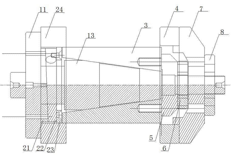
[0038] combined with Figure 1~6 , a kind of slitting disc blade coaxial precision machining special tooling of the present embodiment (such as figure 1 , figure 2 and Figure 6 shown), including mandrel spindle, sleeve unloading device, open taper sleeve 3, taper sleeve fixing mechanism and cutter body pressing mechanism.
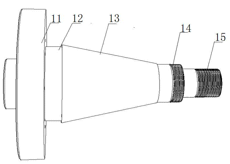
[0039] The mandrel spindle (as image 3 (shown) is a whole, and the mandrel spindle is provided with a pressing plate 11, a sleeve unloading device installation section 12, a tapered transition section 13, a first threaded section 14 and a second threaded section 15 in sequence along its length direction. The pressure plate 11 is a disc structure, and the right side of the pressure plate 11 is uniformly provided with 6 threaded holes along the outer periphery of the sleeve unloading device installation section 12 . The diameter of the sleeve unloading device installation section 12 is consistent with the inner diameter of the sleeve unloading device o...
Embodiment 2
[0053] The special tooling for precision machining of the coaxiality of slitting disc blades in this embodiment is basically the same as that in Embodiment 1, except that the tapered transition section 13 is made of The cylindrical section and the conical section are composed, the circular section is connected with the installation section 12 of the unloading device, the diameter of one end where the conical section joins the cylindrical section is greater than the diameter of the other end, and the taper of the conical section is also 11°. The right side of the pressure plate 11 is evenly provided with 8 threaded holes along the outer periphery of the sleeve unloading device installation section 12, and the first unloading plate 21, the second unloading plate 22 and the third unloading plate 23 8 threaded holes are uniformly opened along the ring body. The method of using the special tooling for coaxial precision machining in this embodiment is the same as that in Embodiment ...
Embodiment 3
[0055] A special tooling for precision machining of the coaxiality of slitting disc blades in this embodiment is basically the same as in Embodiment 2, except that the side where the open taper sleeve 3 and the taper sleeve pressure plate 5 are adjacent is about the central axis Threaded holes are symmetrically opened, and the taper sleeve pressure plate 5 and the open taper sleeve 3 are fixedly connected with bolts on the side adjacent to each other. When the sleeve 3 is unloaded, the open taper sleeve 3 can be pulled out through the taper sleeve pressing plate 5 . The right side of the pressure plate 11 is evenly provided with 10 threaded holes along the outer periphery of the sleeve unloading device installation section 12, and the first unloading plate 21, the second unloading plate 22 and the third unloading plate 23 are uniformly provided with 10 threaded holes. 10 threaded holes are uniformly opened along the ring body. The method of using the special tooling for coaxi...
PUM
 Abstract
Description
Claims
Application Information
 - R&D
- Intellectual Property
- Life Sciences
- Materials
- Tech Scout
- Unparalleled Data Quality
- Higher Quality Content
- 60% Fewer Hallucinations
Browse by: Latest US Patents, China's latest patents, Technical Efficacy Thesaurus, Application Domain, Technology Topic, Popular Technical Reports.
© 2025 PatSnap. All rights reserved.Legal|Privacy policy|Modern Slavery Act Transparency Statement|Sitemap|About US| Contact US: help@patsnap.com


