Brake disk

A brake and disc technology, applied to bicycle accessories, bicycle brakes, etc., can solve the problems of bicycle disc brake pad deformation, brake failure, and weak structural strength of bicycle disc brake pads, so as to avoid deformation or fracture and have better structural strength Effect

Inactive Publication Date: 2013-12-11
温芫鋐
7 Cites 8 Cited by

AI-Extracted Technical Summary

Problems solved by technology

[0004] However, although the heat dissipation method of this kind of structure can increase the ventilation to achieve the effect of heat dissipation, the bicycle disc brake pad is perforated with holes and the structural strength of the bicycle disc brake pad is relatively weak. Bicycle disc brake pads may generate high temperat...

Method used

In actual use, the body 1 of the first embodiment of the present invention is described in detail here, and the body 1 can be combined with the flower hub (not shown) of the bicycle through the plurality of joints 12 to be combined with the bicycle The rim of the bicycle has a linkage relationship, and the user can selectively clamp the brake device to the brake part 11 of the body 1 by controlling a brake device to stop the rim of the bicycle from rotating to achieve the effect of braking. The brake part 11 of 1 is clamped by the brake device when it rotates, and often causes high temperature due to heat generated by friction. The two heat sinks 2 provided by the present invention are respectively arranged on two sides of the body 1 and borrow The main body 1 and the two heat sinks 2 are locked by the plurality of locking pieces 6, and each of the heat sinks 2 is located between the braking part 11 of the main body 1 and the plurality of joint parts 12, so as to shorten the time of heat conduction In this way, the heat generated by the brake part 11 of the main body 1 due to the clamping of the brake device can be conducted to the two heat sinks 2 via the connecting part 13 of the main body 11 to dissipate the heat energy more quickly. In addition, Each heat sink 2 has a plurality of elongated holes 22, and the plurality of long holes 22 communicate with the round hole 21 of the heat sink 2, thereby increasing the surface area of ​​the heat sink 2 in contact with the air, further improving the heat dissipation effect In this way, the main body 1 can be prevented from generating high temperature due to friction, which may even cause the main body 1 to deform or break and cause safety problems such as brake failure. Moreover, when the braking device clamps the main body 1, it may also be clamped to the plurality of The radiating part 14, each of the radiating elements 2 provided by the present invention is in contact with the plurality of radiating parts 14 and partially overlaps with the area of ​​the plurality of radiating parts 14, so that heat energy passes through the plurality of radiating parts 14 as a transmission pipe Conducted to the two heat sinks 2, the heat conduction rate is increased to make the heat dissipation rate better, and the heat can also be prevented from being directly transmitted to the hub of the bicycle through the plurality of joints 12 to increase the temperature of the hub. In addition, the outer diameter of each heat sink 2 is smaller than the outer diameter of the body 1. When the brake device is clamped on the body 1, it will not touch the two heat sinks 2 so that the two heat sinks 2 will not be braked. The clamping of the device causes wear, etc.
In other possible embodiments, as shown in Fig. 4 and Fig. 5, it is shown as the second embodiment of the present invention, and the difference with the aforementioned first embodiment is that the body 3 can be placed on any two adjacent heat dissipation At least one convex portion 32 is formed radially between the portions 31 toward the central axis to increase the surface area of ​​the main body 3 in contact with the air so that the heat dissipation effect is better. In addition, in this embodiment, the heat dissipation element 4 is not provided with the long hole, the side of the radiator 4 facing away from the body 3 protrudes with a plurality of ribs 41 to increase the surface area of ​​the radiator 4 in contact with the air to further improve the heat dissipation effect, and the plurality of ribs 41 are arranged around the central axis The protruding ribs 41 are arranged at intervals, and the extending direction of each protruding rib 41 is parallel to the central axis.
It is worth mentioning that since the plurality of joints 12 of the body 1 are surrounded by star-shaped holes, a plurality of joints 12 are formed between the annular part of the body 1 and the plurality of joints 12. A hollow portion 15, when the two heat sinks 2 are arranged on the opposite sides of the body 1, since the joint portion 12 is clamped between the two heat sinks 2, so that the two heat sinks 2 correspond to the The position of the hollow part 15 has a gap to form the effect similar to a ventilation hole, thereby further increasing the surface area of ​​the two heat sinks 2 in contact with the air, so that when the bicycle drives the body 1 to rotate during travel, the air can The air flows toward the central axis through the gap between the two cooling elements 2 to increase the ventilation effect and further improve the heat dissipation effect.
[0031] The two heat sinks 2 are respectively arranged on opposite sides of the body 1 on the central axis. More specifically, the body 1 has two opposite sides, and the two heat sinks 2 are respectively arranged on the body 1 The opposite two sides, thereby increasing the heat dissipation rate so that the heat dissipation effect is better and the structural strength of the body 1 is better. In addition, the weight of the bicycle can be averaged without the center of gravity shifting. Compared with mater...

Abstract

The invention provides a brake disk, which comprises a body and at least two heat dissipation components. The body is provided with an annular part, and a middle axle is defined by the body by the annular part. The annular part is provided with a brake part to be clamped by a brake device of a bicycle; at least one joint part extends towards the middle axle from the body and is combined with a flower hub of the bicycle; at least one junction part is arranged between the joint part and the brake part; each junction part is provided with at least one first fixed part; the two heat dissipation components are respectively arranged at two opposite sides of the body; each heat dissipation component is provided with at least one second fixed part to be fixedly combined with the at least one first fixed part of each junction part, and thus, when the brake part is clamped by the brake device, the heat dissipation components are capable of transferring heat, generated by the body due to braking, to the heat dissipation components by the at least one junction part to achieve a better heat dissipation effect.

Application Domain

Technology Topic

Image

  • Brake disk
  • Brake disk
  • Brake disk

Examples

  • Experimental program(1)

Example Embodiment

[0027] The following examples are only used to illustrate the possible implementation aspects of the present invention, but they are not intended to limit the scope of protection of the present invention, and are described first.
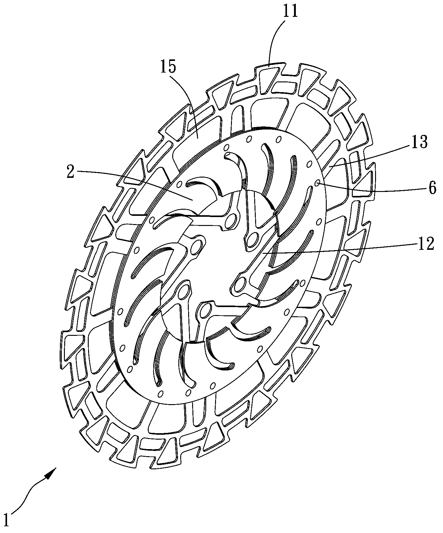
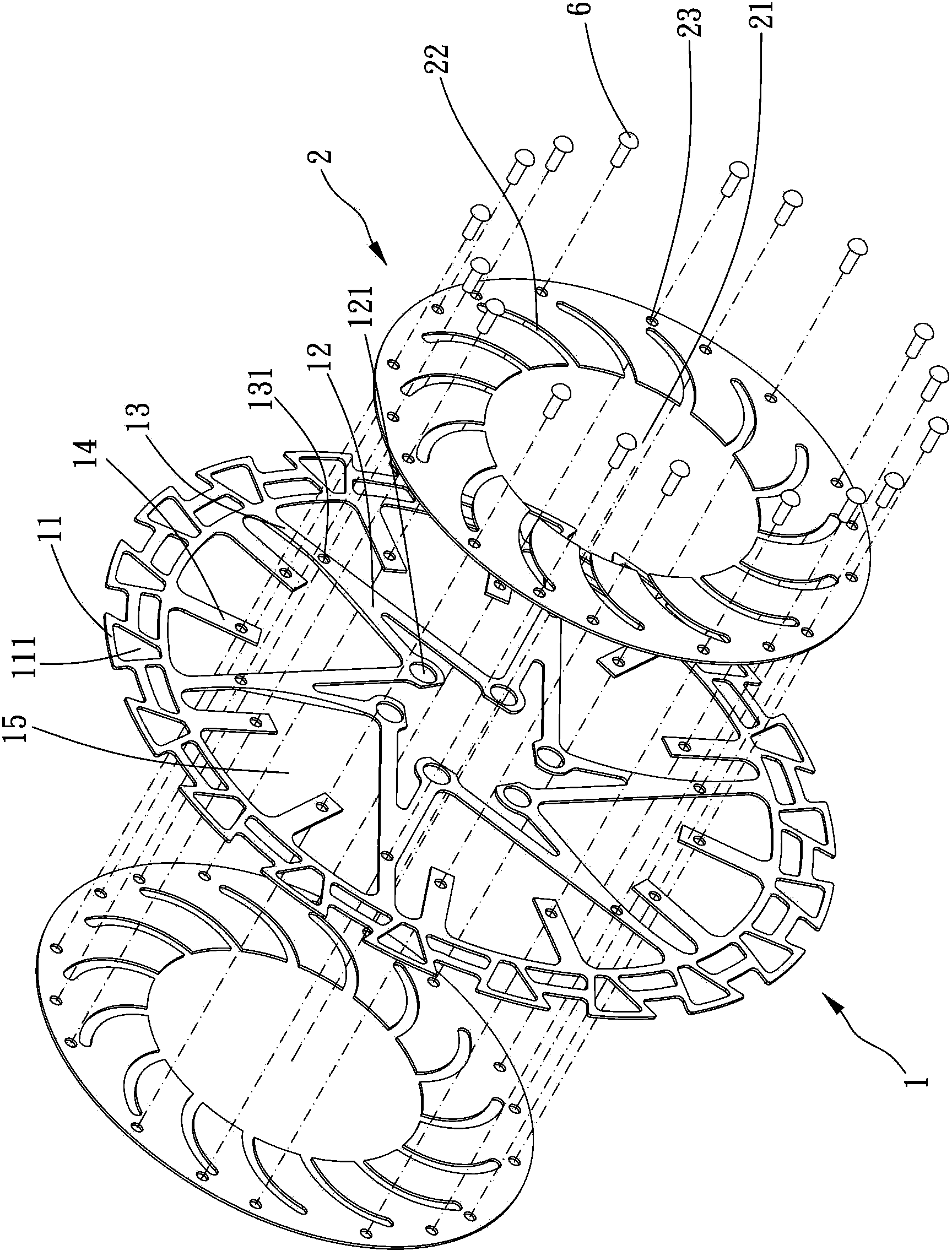
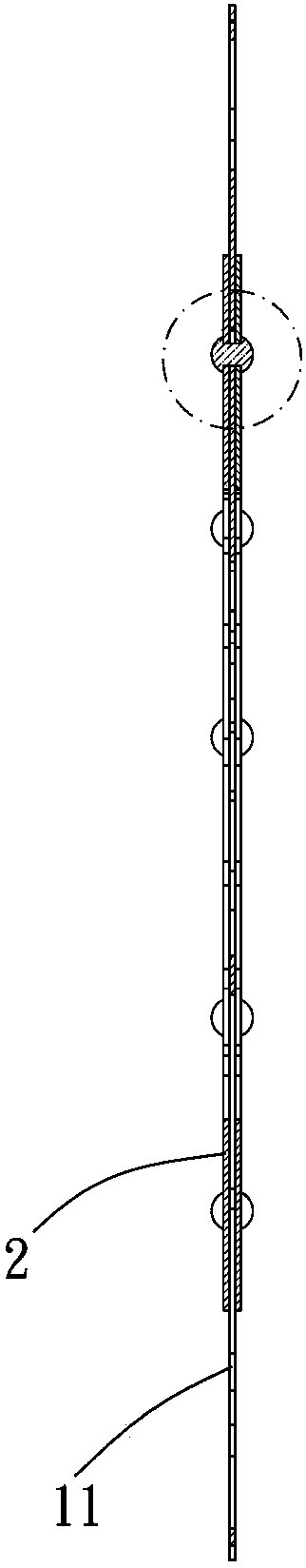
[0028] Please refer to Figure 1 to Figure 3 , Which is shown as a brake disc according to the first embodiment of the present invention, includes a body 1 and at least two heat sinks 2.
[0029] The main body 1 is a one-piece body and has an annular part. The main body 1 defines a central axis by the annular part. The annular part is further away from the central shaft and has a braking portion 11 for a bicycle brake device to clamp. Preferably, the braking portion 11 of the main body 1 is provided with a plurality of heat dissipation holes 111 in a direction parallel to the center axis, and the plurality of heat dissipation holes 111 are arranged around the center axis, thereby increasing the braking portion 11 and The air contact surface area. When the braking portion 11 of the main body 1 is clamped by the braking device, the heat dissipation holes 111 of the braking portion 11 can make the heat generated by the braking portion 11 leave the main body 1 more quickly. On the one hand, as compared with other metal materials, the price of iron is lower and its structural strength is better. Therefore, the body 1 is preferably made of iron, which can not only reduce the manufacturing cost but also prevent the brake part 11 from being braked. The clamping of the device generates heat, which further causes problems such as deformation.
[0030] The body 1 has at least one coupling portion 12 extending toward the bottom bracket for coupling with the hub of the bicycle. There is at least one coupling portion 13 between the coupling portion 12 and the braking portion 11. In this embodiment, the main body 1 has There are a plurality of connecting portions 12, and each connecting portion 12 and the braking portion 11 have a connecting portion 13 between them. More specifically, each of the connecting portions 12 is generally V-shaped or Y-shaped and has two arms. The connecting part of the support arm is combined with the connecting portion 13, more clearly, the braking portion 11, the plurality of connecting portions 13 and the plurality of connecting portions 12 are integrally formed, and the body 1 faces from the annular portion The central axis extends radially to form the plurality of connecting portions 13, and each of the connecting portions 13 further extends toward the central axis to form the two arms. It should be noted that each of the arms and the adjacent joining portion 12 The adjacent arm is connected to make the plurality of joints 13 generally have a radial structure, so that the plurality of joints 12 are surrounded to form a star-shaped hole, and in any two adjacent joints 12, A coupling hole 121 is provided at the joint of the two arms connected to each other from different coupling parts 12, whereby the plurality of coupling holes 121 are used for coupling and locking with the hub of the bicycle. Each of the connecting portions 13 is provided with at least one first fixing portion. More specifically, the first fixing portion includes a first through hole 131. One end of each connecting portion 13 closer to the central axis is connected to the central axis. The first through hole 131 penetrates in a parallel direction. Of course, in other possible embodiments, the plurality of coupling portions may not be integrally formed with the braking portion and the plurality of coupling portions, but it does not matter that they are detachably provided on the plurality of coupling portions.
[0031] The two heat sinks 2 are respectively disposed on two opposite sides of the main body 1 on the central axis. More specifically, the main body 1 has two opposite sides, and the two heat sinks 2 are respectively disposed on two opposite sides of the main body 1. Surface, thereby increasing the heat dissipation rate, the heat dissipation effect is better, and the structural strength of the body 1 is better. In addition, the weight of the bicycle can be averaged without the center of gravity shift. Compared with other materials , Iron and aluminum have better conduction effects, so the two heat sinks 2 are preferably made of aluminum or aluminum alloy, so as to increase the heat conduction rate and further improve the heat conduction effect. The structure of the two heat sinks 2 and the The combination of the main body 1 is the same, and only a single heat sink 2 is used as an illustration below. In this embodiment, the heat dissipating element 2 is generally annular and arranged coaxially with the main body 1. The heat dissipating element 2 has a circular hole 21 in the center, and each heat dissipating element 2 is provided with a plurality of lengths around the central axis. Each of the long holes 22 communicates with the circular hole 21, and the plurality of long holes 22 are divergently arranged at intervals. It should be noted that the outer diameter of the heat sink 2 is smaller than that of the main body 1. The outer diameter and the heat sink 2 are substantially located between the brake portion 11 and the plurality of coupling portions 12, so that when the brake device is clamped on the body 1, the brake device will not be stuck to the heat sink 2 Therefore, the heat sink 2 is less susceptible to wear and damage, and the heat generated by the braking part 11 can be directly transferred to the two heat sinks 2 via the connecting part 13. The heat dissipating member 2 is provided with at least one second fixing portion for being combined and fixed with the first fixing portion of each connecting portion 13. Preferably, the heat dissipating member 2 is provided with a plurality of second fixing portions, the plurality of second fixing portions The number and positions of the fixing parts correspond to the number and positions of the first fixing parts of the plurality of connecting parts 13 of the main body 1. More specifically, each of the second fixing parts includes a second perforation 23, the The plurality of second perforations 23 are arranged around the central axis and correspond to the plurality of first perforations 131 of the first fixing portion. Preferably, the annular portion of the main body 1 is closer to the central axis and radially protrudes toward the central axis with a plurality of heat dissipation portions 14, the plurality of heat dissipation portions 14 are arranged around the central axis and the plurality The radiating portions 14 are arranged at intervals, and each radiating portion 14 is substantially a rectangular sheet-like structure. More clearly, the tangential direction of the connection between each radiating portion 14 and the annular portion of the body 1 is the same as The length extension direction of each heat dissipation part 14 is generally vertical. In addition to being connected to the plurality of coupling parts 13, each heat dissipation element 2 is further connected to the plurality of heat dissipation parts 14 and each heat dissipation element The area of ​​2 is partially overlapped with the area of ​​each of the radiating portions 14, whereby when the braking portion 11 is clamped by the braking device to generate heat, each of the radiating portions 14 can provide a pipe for heat conduction to the radiating member 2 Improve the heat dissipation efficiency.
[0032] It is worth mentioning that, since the plurality of joint portions 12 of the main body 1 are surrounded by a star-shaped hole, a plurality of hollow portions are formed between the annular portion of the main body 1 and the plurality of joint portions 12 15. When the two heat sinks 2 are arranged on two opposite sides of the main body 1, since the joint portion 12 is clamped between the two heat sinks 2, the gap between the two heat sinks 2 corresponds to the hollow portion 15 There is a gap at the position to form a function similar to a vent hole, thereby further increasing the surface area of ​​the two heat sinks 2 in contact with the air, so that when the bicycle drives the body 1 to rotate while traveling, the air can dissipate heat through the two The gap between the parts 2 flows toward the central axis to increase the ventilation effect and further improve the heat dissipation efficiency.
[0033] In this embodiment, such as figure 2 and Figure 3A As shown, the combination of each of the heat sink 2 and the connecting portion 13 is to use a fastener 6 to lock the two heat sinks 2 and the body 1 together. More clearly, the fastener 6 is a rivet. It has a head and a body, wherein the diameter of the head is greater than the diameter of the body, and the locking member 6 passes through the second through hole 23 of one of the heat sinks 2 and the connecting portion 13 with the body in sequence The first through hole 131 and the second through hole 23 of the other heat sink 2, and the body is knocked or similar to make the two heat sinks 2 and the main body 1 interlock and lock each other, of course, there are other possibilities In the embodiment, it is not limited to use riveting to lock the fastener with the main body 1, and it is also possible to lock the two heat sinks and the main body by a screw lock or similar fixing method. In addition, each The heat sink 2 and the heat sink 14 are also riveted and locked between the heat sink 14 of the body 1 and the two heat sinks 2 by using the above-mentioned combination method, so that the plurality of heat sinks 14 and the heat sink 2 Overlapping and contacting each other, when the braking portion 11 is clamped by the braking device, heat energy can be conducted to the two heat dissipation members 2 via the heat dissipation portion 14, so that the heat dissipation effect is better.
[0034] In other possible embodiments, such as Figure 4 and Figure 5 As shown, it is shown as the second embodiment of the present invention. The difference from the aforementioned first embodiment is that the body 3 can extend radially toward the central axis between any two adjacent heat dissipation portions 31 to form at least one The convex portion 32 increases the surface area of ​​the main body 3 in contact with the air, so that the heat dissipation effect is better. In addition, in this embodiment, the heat dissipation member 4 is not provided with the elongated hole, and the heat dissipation member 4 is protruding from the side of the main body 3 There are a plurality of ribs 41 to increase the surface area of ​​the heat sink 4 in contact with air to further improve the heat dissipation effect. The plurality of ribs 41 are arranged at intervals around the central axis, and the extending direction of each rib 41 is Parallel to the central axis.
[0035] It is understandable that in the third embodiment of the present invention, please refer to Image 6 The difference from the aforementioned first and second embodiments is that each of the heat sink 5 includes a plurality of heat dissipation blocks 51, and the plurality of heat dissipation blocks 51 are sequentially arranged on the body 3 around the central axis, each The heat dissipation block 51 is provided with at least one second fixing portion, each of the second fixing portions includes a second through hole 511, and each of the heat dissipation blocks 51 has its second fixing portion and the first connecting portion 33 of the main body 3. The fixing parts are combined with each other to lock each heat sink 51 and the main body 3 to each other. The combination of each heat sink 51 and the main body 3 is the riveting method described in the first embodiment. To add more details, the side of each heat dissipation block 51 facing away from the main body 3 is protrudingly provided with a plurality of ribs 512 to increase the surface area of ​​the heat dissipation block 51 in contact with the air, so that the heat dissipation effect is better, and each protrusion 512 extends convexly The direction is parallel to the central axis.
[0036] In actual use, the main body 1 of the first embodiment of the present invention is described in detail. The main body 1 can be combined with a bicycle hub (not shown) through the plurality of coupling parts 12 to be connected to a bicycle rim With a linkage relationship, the user can selectively make the brake device clamp the brake portion 11 of the body 1 by controlling a brake device to stop the rim of the bicycle from rotating to achieve the effect of braking, due to the brake of the body 1 The part 11 is clamped by the brake device when it is rotating, and heat is often generated by friction, resulting in high temperature. The two heat sinks 2 provided by the present invention are provided on the two sides of the main body 1 and rely on the plural A locking member 6 locks the main body 1 and the two heat dissipation elements 2, and each of the heat dissipation elements 2 is located between the braking portion 11 of the main body 1 and the plurality of coupling portions 12, thereby shortening the heat conduction path, so As a result, the heat generated by the braking portion 11 of the main body 1 due to the clamping of the braking device can be conducted to the two heat dissipation members 2 through the connecting portion 13 of the main body 11, so that the heat can be quickly dissipated. The member 2 has a plurality of long holes 22, and the plurality of long holes 22 are communicated with the circular holes 21 of the heat dissipation member 2, thereby increasing the surface area of ​​the heat dissipation member 2 in contact with the air, so that the heat dissipation effect is further improved. To avoid the high temperature of the main body 1 due to friction, which may even cause the main body 1 to deform or break and cause brake failure and other safety problems. Furthermore, when the main body 1 is clamped by the braking device, it may be clamped to the plurality of heat dissipation parts 14 , Each of the heat sinks 2 provided by the present invention contacts the plurality of heat dissipation portions 14 and overlaps with the area of ​​the plurality of heat dissipation portions 14, so as a transmission pipe, heat energy is conducted to the plurality of heat dissipation portions 14 The two heat-dissipating members 2 increase the heat conduction rate and make the heat dissipation rate better, and can also prevent the heat from being directly conducted to the hub of the bicycle through the plurality of joints 12 to increase the hub temperature. In addition, the outer diameter of each heat sink 2 is smaller than the outer diameter of the main body 1. When the braking device is clamped on the main body 1, the two heat sinks 2 will not be touched so that the two heat sinks 2 will not be braked. The clamping of the device causes wear and so on.
[0037] In summary, the present invention provides a brake disc with a simplified structure and practicality. The plurality of heat sinks not only shortens the heat conduction path of the brake part of the body due to the clamping of the brake device, but also It is directly conducted to the two heat dissipation elements through the connecting portion, so that the conduction rate is better and the heat dissipation efficiency is further improved, and the structural strength of the main body can also be enhanced, which is a very advanced effect.

PUM

no PUM

Description & Claims & Application Information

We can also present the details of the Description, Claims and Application information to help users get a comprehensive understanding of the technical details of the patent, such as background art, summary of invention, brief description of drawings, description of embodiments, and other original content. On the other hand, users can also determine the specific scope of protection of the technology through the list of claims; as well as understand the changes in the life cycle of the technology with the presentation of the patent timeline. Login to view more.

Similar technology patents

Classification and recommendation of technical efficacy words

  • Good structural strength
  • Prevent deformation and breakage

Moulding method of variable-density broadband wave-transparent quartz composite ceramic antenna housing body

ActiveCN104446584AGood structural strengthImprove impregnation composite effectBroadbandVariable density
Owner:湖北三江航天江北机械工程有限公司

Reinforcing part adding position design method, forming method, storage medium and system

PendingCN114305748AImprove local stiffnessPrevent deformation and breakageOthrodonticsEngineeringMechanical engineering
Owner:WUXI EA BIOTECHNOLOGY LTD

Elastic ring fine-tuning bra

ActiveCN109717522AImprove experiencePrevent deformation and breakageBrassieresEngineeringFine-tuning
Owner:广州市熳洁儿服饰有限公司
Why Eureka
Try Eureka