
Electrical machine having centrally disposed stator

Inactive Publication Date: 2007-02-01
TELEFLEX CANADA
View PDF15 Cites 3 Cited by
  • Summary
  • Abstract
  • Description
  • Claims
  • Application Information

AI Technical Summary

Benefits of technology

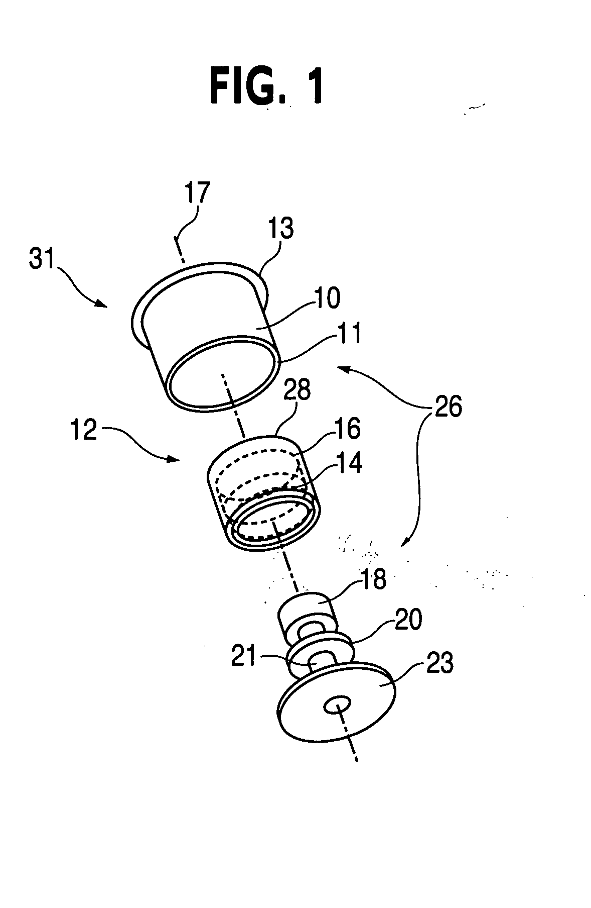
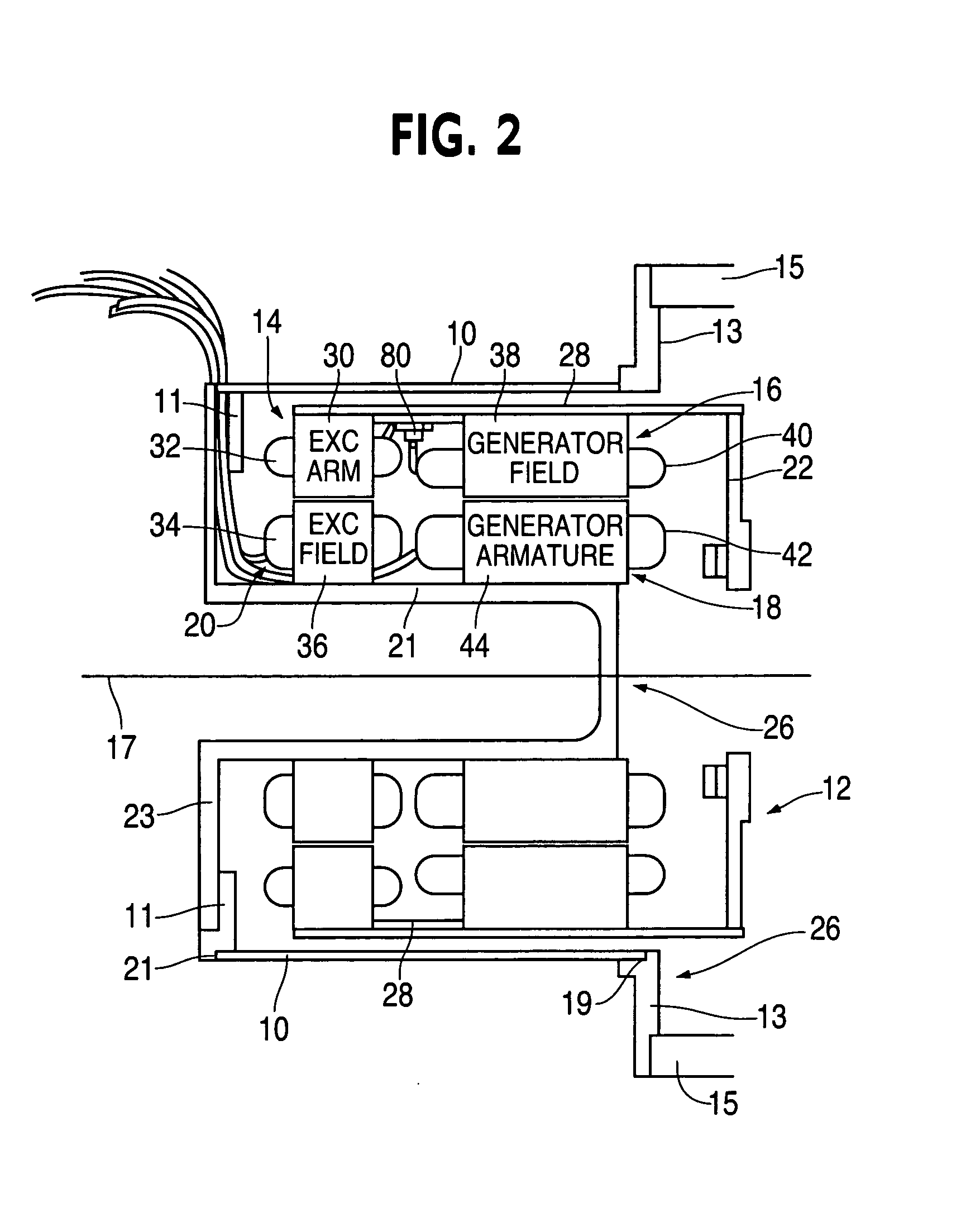
[0010] The inside-out geometry of the present embodiment provides many advantages. It allows for elimination of a generator shaft and generator bearing. The relatively large diameter of the rotor mounting member results in very good structural strength. This eliminates the need for an outboard support bearing, as is commonly known in the art, and permits a cantilevered design.
[0011] A high rotational inertia is also achieved with the inside-out geometry. This fulfills a need that exists when the generator is used on small diesel engines. Since the rotor lies radially outwardly of the stator windings, it has the necessary rotational inertia for small diesel engines without adding excessive weight.
[0012] Another advantage of the inside-out geometry is its thermal characteristic. The location of the generator field winding around an inner periphery of the rotor housing, next to the stator housing, provides significantly more cooling surface than if it was located radially within the stator windings. The generator field winding can expel its heat losses to the surrounding stator housing. Additionally, the inside-out geometry allows for air ventilation openings in the rotor to allow for some passive circulation of air in and around the rotor windings to provide cooling.

Problems solved by technology

This limits the usefulness of the electrical generator in many applications requiring the excited magnetic field to be controlled, which is not possible when using permanent magnets.
This complicates the mounting of the electrical generator on a rotational means, such as found on an engine.
This decreases the reliability and rotational speed of such generators.

Method used


Image

  • Electrical machine having centrally disposed stator
  • Electrical machine having centrally disposed stator
  • Electrical machine having centrally disposed stator

Examples


second embodiment

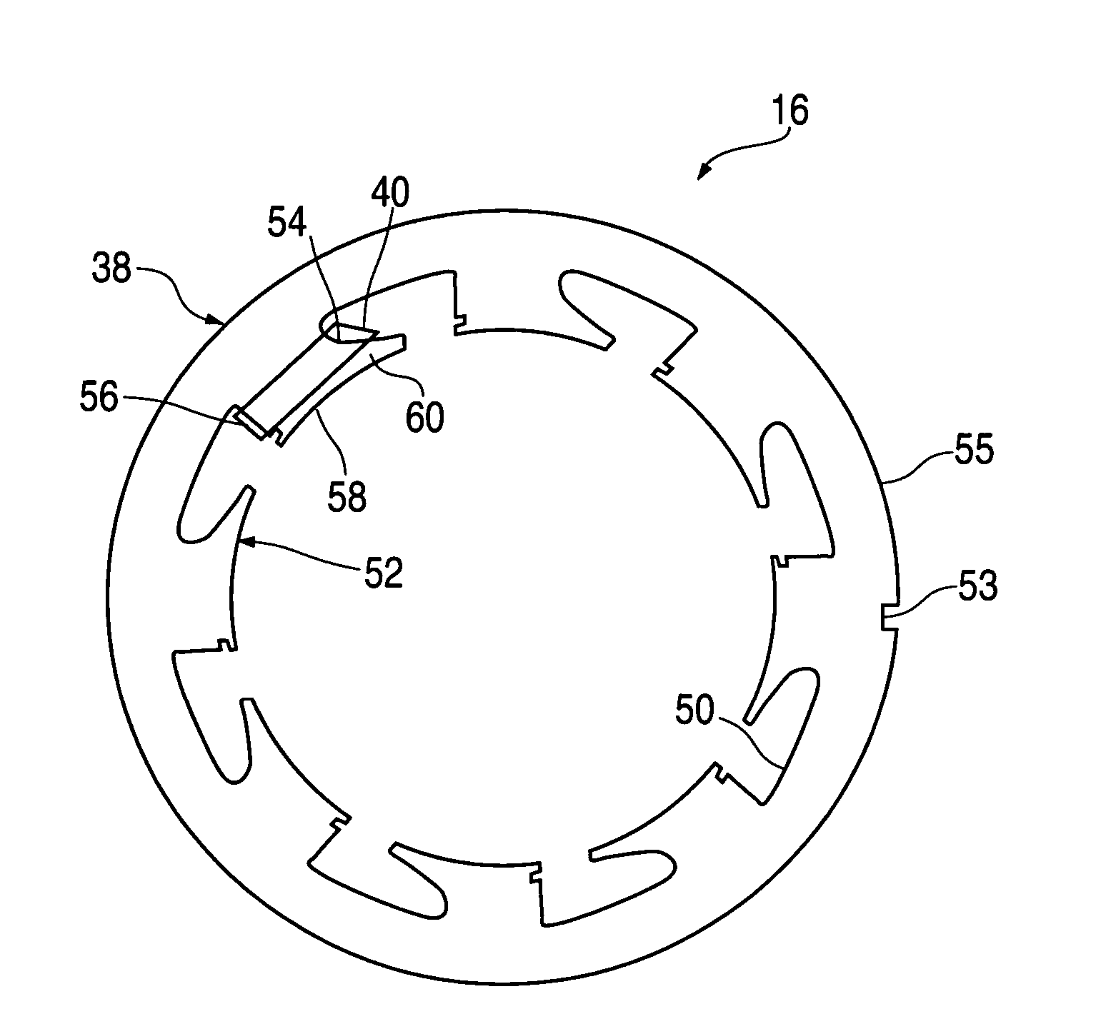
[0052] The generator field coils 40.1 in this example are machine wound on the plurality of winding members 64, after which each said winding member 64 is engaged with one of said recesses 63 of the annular core 38.1. The advantages of this second embodiment of the generator field winding 16.1 are the same as the previous embodiment above. Furthermore, the annular core 38.1 can comprise either solid core technology or laminations.

[0053] In another embodiment of the present invention illustrated in FIG. 8, wherein like parts have like reference numerals with the extension “0.2”, an electrical generator 31.2 is connected to a flywheel 90 and an engine block 92. The electrical generator 31.2 is similar to the electrical generator 31 of the prior embodiment. The flywheel 90 is a rotatable member for rotating the rotor. The engine block 92 is a stationary member for mounting the stator.

[0054] Another advantage of the present invention is the ability to quickly mount the electrical gener...

first embodiment

[0056] Another embodiment of the present invention is illustrated in FIGS. 9-14, wherein like parts have like reference numerals with the extension “0.3”. This embodiment is similar to the Referring first to FIGS. 9-11, there is shown a rotor 12.3 including an exciter armature winding 14.3, a generator field winding 16.3 and a rotor housing 28.3. A rectifier assembly 98 is connected to an end of the rotor 12.3. In this example, the rectifier assembly 98 includes two bridge rectifiers and a termination assembly mounted on a printed circuit board (PCB). The bridge rectifiers are located 120 degrees apart along an outer periphery of the PCB, the termination assembly is mounted equidistant from the two bridge rectifiers along the same periphery.

[0057] Now referring to FIGS. 12-14, there is shown a stator 26.3. The stator 26.3 includes a central member 21.3, an end member 23.3, an exciter field winding 20.3 and a generator armature winding 18.3.


PUM


Abstract

An electrical generator comprising a stator having stator windings and a rotor having rotor windings. The rotor and the rotor windings extend about the stator windings. The rotor includes an annular rotor housing. On an inside of the rotor housing are mounted the rotor windings. The stator includes an end member with a central member extending therefrom. The stator windings are mounted on the central member. The stator also includes an annular stator housing that extends about the central member, including the stator windings, and the rotor. The end member attaches to the stator housing thereby positioning the stator windings in a central location. The stator housing and the end member enclose the stator windings and the rotor windings therein. The rotor housing further includes a rotor mounting member on an end. The stator housing includes a stator mounting member on an end thereof, and a stator windings mounting member on an opposite end. The stator windings include an exciter field winding and a generator armature winding. The rotor windings include an exciter armature winding and a generator field winding. The exciter armature winding is disposed radially outwardly from and adjacent to the exciter field winding. The generator field winding is disposed radially outwardly from and adjacent to the exciter armature winding.

Description

BACKGROUND OF THE INVENTION [0001] This invention relates to electrical machines having centrally disposed stators and, in particular, to electrical generators having centrally disposed stators. [0002] Conventional electrical generators have made use of a permanent magnet to provide a DC magnetic field, such as disclosed in U.S. Pat. No. 4,900,959, issued Feb. 13, 1990 to Drinkut et al. This limits the usefulness of the electrical generator in many applications requiring the excited magnetic field to be controlled, which is not possible when using permanent magnets. As disclosed in Drinkut et al., conventional electrical generators further include a generator shaft and bearing to attach to the rotor for rotation. This complicates the mounting of the electrical generator on a rotational means, such as found on an engine. Additionally, these electrical generators have made use of DC current collection rings to route the generated power off of the rotor to be used by a load. This decre...

Claims


Application Information

Patent Timeline
IPC IPC(8): H02K1/00H02K1/28
CPCH02K19/38H02K19/22
Inventor SYVERSON, CHARLES D.GOTMALM, CHRISTER
Owner TELEFLEX CANADA
Learn More