Water cooling system for steel plate quenching apparatus

A technology of quenching device and water cooling system, applied in the direction of quenching device, heat treatment equipment, furnace, etc., can solve the problems of cooling speed difference, affecting the overall quality of quenched steel plate, etc., achieve fast cooling speed, avoid quality defects of quenched steel plate, and uniform quenching of steel plate Effect

Inactive Publication Date: 2013-12-11
CERI PHOENIX INDAL FURNACE CO TD +1
View PDF3 Cites 3 Cited by
  • Summary
  • Abstract
  • Description
  • Claims
  • Application Information

AI Technical Summary

Problems solved by technology

[0005] The other is the swing bench structure. The crane places the heated steel plate on the horizontal swing bench above the quenching tank, and the swing bench rotates around one end, so that the swing bench drives the steel plate to swing downward in the quenching tank. Stop at about 45°, at this time the steel plate is completely submerged in the water tank, thus completing the quenching heat treatment process of the steel plate entering and exiting the water; the device can realize automatic production and fully meet the quenching heat treatment requirements of medium and heavy plates and special thick plates; however, With this quenching method, when the swinging table drives the steel plate to immerse in the quenching tank, a large number of air bubbles will be generated on the upper and lower surfaces of the steel plate, and these air bubbles are difficult to separate from the steel plate by buoyancy. It prevents the contact between the partial surface of the steel plate and the cooling water, making the cooling rate of these local surfaces different from other surfaces without air bubbles, which will affect the overall quality of the quenched steel plate

Method used


Image

  • Water cooling system for steel plate quenching apparatus
  • Water cooling system for steel plate quenching apparatus
  • Water cooling system for steel plate quenching apparatus

Examples


Embodiment Construction

[0032] In order to have a clearer understanding of the technical features, purposes and effects of the present invention, the specific implementation manners of the present invention will now be described with reference to the accompanying drawings.

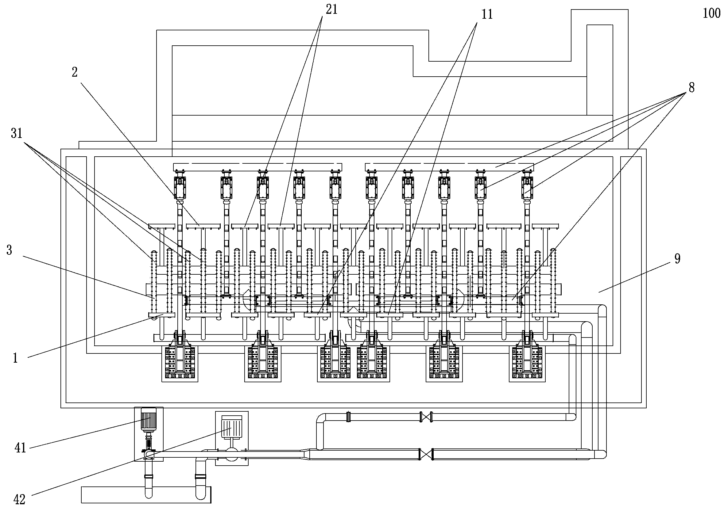
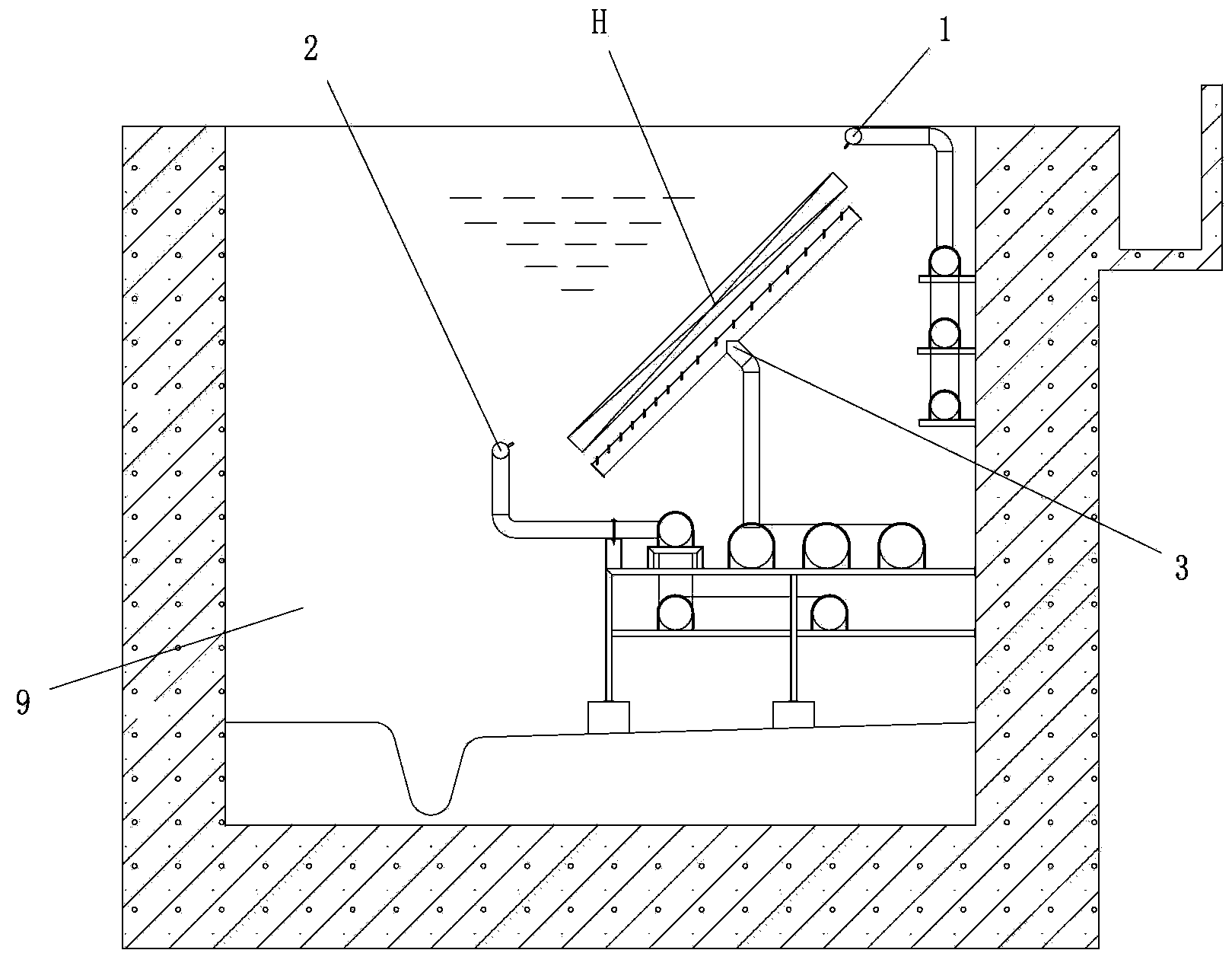
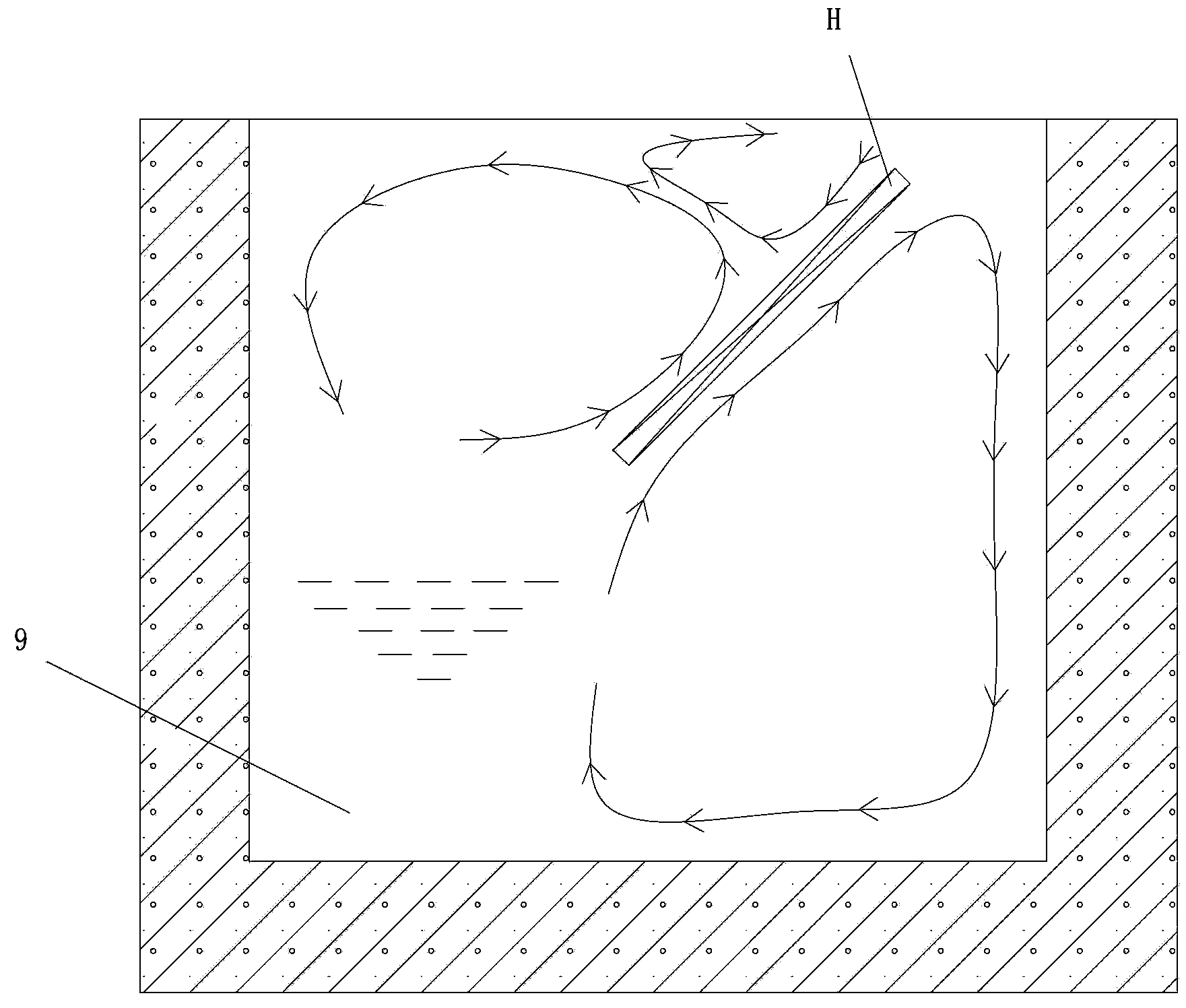
[0033] Such as figure 1 , figure 2 and image 3 As shown, the present invention proposes a water cooling system 100 of a steel plate quenching device; the steel plate quenching device is a swing type quenching device, and the swing type quenching device includes a quenching tank 9 and a swinging platform that is rotatably connected to the side wall of the quenching tank 8. The swing table 8 is composed of a plurality of longitudinal beams arranged at intervals and a plurality of cross beams arranged at intervals; The water device 2 and the third water spray device 3 constitute; the first water spray device 1, the second water spray device 2 and the third water spray device 3 are respectively connected to the water pump 41 or 4...


PUM


Abstract

The invention provides a water cooling system for a steel plate quenching apparatus. The water cooling system is composed of a first water spraying device, a second water spraying device and a third water spraying device all arranged in a quenching tank, wherein the first water spraying device is arranged above the top of the upper surface of a steel plate at an inclined quenching position and composed of a plurality of first nozzles arranged at intervals along the edge of the top of the steel plate upper surface, the second water spraying device is arranged above the bottom of the upper surface of the steel plate at the inclined quenching position and composed of a plurality of second nozzles arranged at intervals along the edge of the bottom of the steel plate upper surface, and the third water spraying device is arranged below the lower surface of the steel plate at the inclined quenching position and composed of a plurality of third nozzles horizontally or vertically arranged at intervals along the steel plate lower surface. The water cooling system can take away considerable bubbles generated on the surface of the steel plate through washing in a short time, so quenching of the steel plate is more uniform, and quality defects of the quenched steel plate caused by different local cooling rates are avoided.

Description

technical field [0001] The invention relates to metallurgical machinery and equipment, in particular to a water cooling system for a steel plate quenching device used for heat treatment and quenching of extra-wide and extra-thick steel plates. Background technique [0002] After entering the 21st century, especially in recent years, with the rapid development of my country's nuclear energy, military industry, shipbuilding industry, thermal power generation, bridge construction, oil and gas development and transportation, automobiles and construction machinery and other industries, various specifications and high The demand for high-performance medium-thick plates and extra-thick plates is increasingly strong; especially the demand for extra-wide and extra-thick quenched plates is increasing. Based on the huge demand for special heat-treated plates in the current market, it is imminent to develop a fully automatic and efficient steel plate quenching device. In recent years, m...

Claims


Application Information

Patent Timeline
Patent Type & Authority Applications(China)
IPC IPC(8): C21D1/63C21D9/46
Inventor 徐永义杨三堂胡文超张省现王珂
Owner CERI PHOENIX INDAL FURNACE CO TD
Why Eureka
Try Eureka