Heat treatment device for machine tool spindle production

A heat treatment device and a technology for machine tool spindles, which are applied in the field of machine tools, can solve problems such as uneven quenching, affecting the physical properties of the spindle, and the inability to spray lye, etc., to achieve improved quenching effects, good application prospects, and good use effects

Inactive Publication Date: 2021-03-02
汪斯宏
View PDF0 Cites 3 Cited by
  • Summary
  • Abstract
  • Description
  • Claims
  • Application Information

AI Technical Summary

Problems solved by technology

[0003] The existing heat treatment device usually directly sprays lye to the surface of the rotary shaft body by spraying during use, which requires a large amount of lye to be sprayed onto the rotary shaft body, resulting in waste of lye and high quenching costs; secondly , it cannot spray lye on the bottom surface of the rotary shaft body, resulting in uneven cooling, incomplete cooling, affecting the cooling effect, and then affecting the surface strength division of the main shaft, resulting in uneven quenching and affecting the subsequent physical properties of the main shaft ; And then propose a heat treatment device for machine tool spindle production

Method used


Image

  • Heat treatment device for machine tool spindle production
  • Heat treatment device for machine tool spindle production

Examples


Embodiment 1

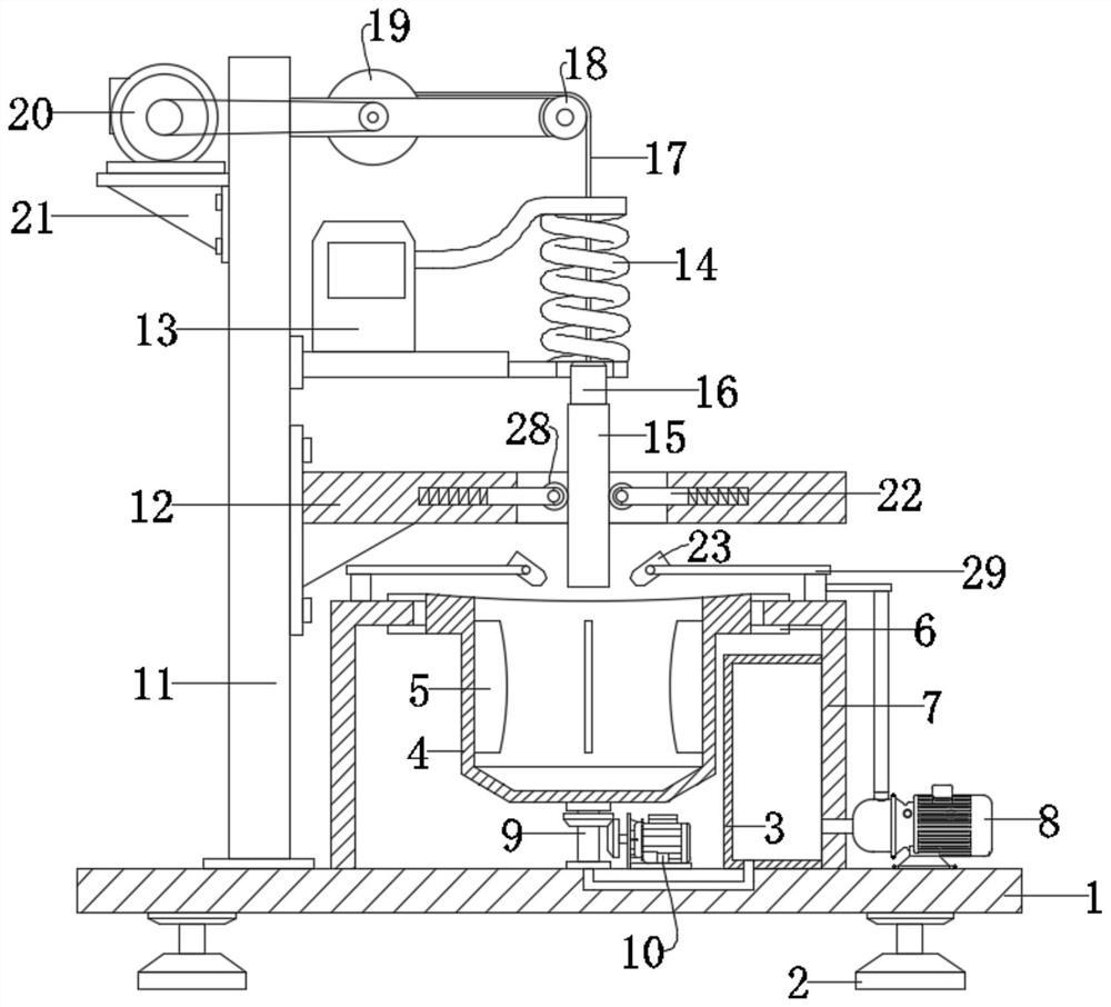
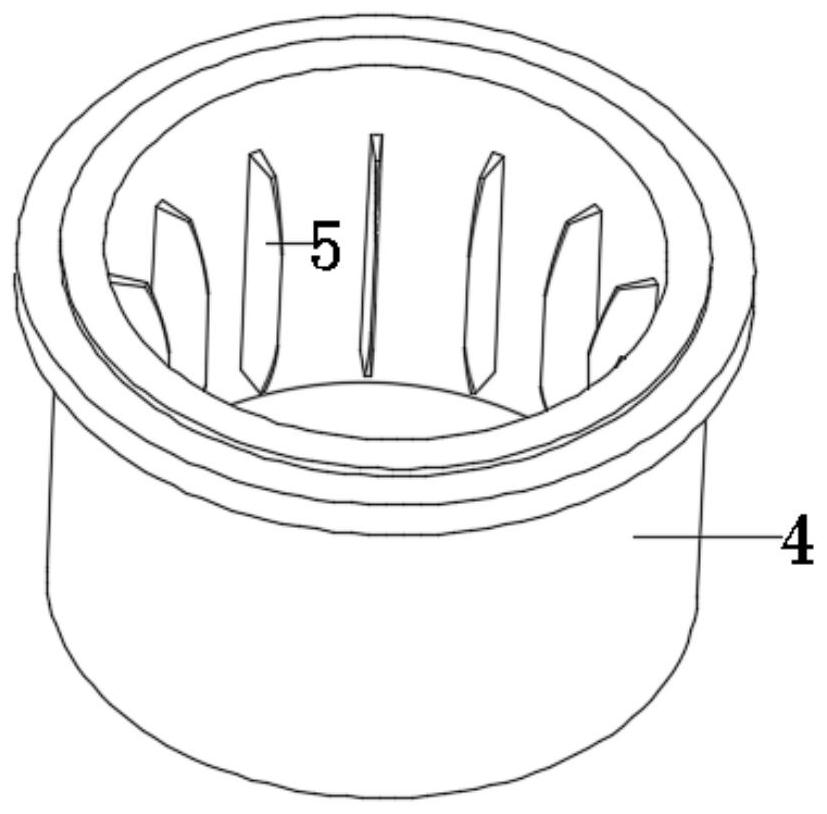
[0020] see Figure 1-2 , a heat treatment device for machine tool spindle production, comprising a base plate 1, a main shaft 15 and a quenching box 4, wherein a support 7 is fixedly connected to the base plate 1, a circular hole is provided at the center of the support 7, and the side of the quenching box 4 The side is fixedly connected with a block 6, and the block 6 is set on the edge of the circular hole, so that the quenching box 4 can rotate along the bracket 7, and a driving device is installed between the bottom plate 1 and the box body, so The driving device acts in the quenching box 4 to further drive the rotation of the quenching box 4; the base plate 1 is fixedly connected with a support 7, and the support 7 is fixedly connected with a carrier plate 12, and the carrier plate 12 is provided with a through hole , the main shaft 15 can pass through the through hole, and a positioning assembly is installed on the carrier board 12, and the positioning control of the mai...

Embodiment 2

[0027] On the basis of the above-mentioned embodiments of this embodiment, the positioning assembly is further explained, wherein, the positioning assembly includes a guide wheel 28 and a sliding rod 22; Elastically installed between the carrier plate 12, three groups of sliding rods 22 are evenly arranged on the carrier plate 12 along the circumference of the through hole on the carrier plate 12; specifically, when the main shaft 15 passes through the through hole, the three groups The rollers can effectively realize the positioning of the main shaft 15, thereby effectively improving the actual use effect of the device.

[0028]The working principle of the present invention is: during the use of the device, the electromagnet 16 is adsorbed on the end of the main shaft 15, thereby realizing the relative fixation between the main shaft 15 and the pull cord 17; Rotate, and then realize the lifting of the main shaft 15; Specifically, on the inner wall of the quenching box 4, a nu...


PUM


Abstract

The invention discloses a heat treatment device for machine tool spindle production. The heat treatment device comprises a bottom plate, a spindle and a quenching box. A round hole is formed in the center position of a support. The side edge of the quenching box is fixedly connected with a clamping block. The clamping block is arranged on the edge of the round hole. The quenching box can rotate along the support. A positioning assembly is arranged on a carrier plate. A heating device is arranged above the carrier plate. According to the device, a plurality of blade plates are fixedly connectedto the inner wall of the quenching box, and therefore when the quenching box rotates, the blade plates further drive quenching liquid in a box body to rotate, during spindle quenching, the rotary quenching liquid acts on the spindle, the single-layer cross section of the spindle is quenched uniformly, and the actual quenching effect of the spindle is further improved. Meanwhile, the quenching liquid enters a water storage tank through a pipeline through a water pump and then enters an atomization sprayer to be sprayed to the spindle, the heated spindle is pretreated, and good application prospects are achieved.

Description

technical field [0001] The invention relates to the field of machine tools, in particular to a heat treatment device for the production of machine tool spindles. Background technique [0002] During the processing of the rotary shaft of the machine tool, it needs to be quenched to transform the cold austenite into martensite or bainite to obtain a martensite or bainite structure, so as to greatly improve the rigidity of the rotary shaft. Hardness, wear resistance, fatigue strength and toughness, etc., so as to meet the different needs of the rotary shaft. [0003] The existing heat treatment device usually directly sprays lye to the surface of the rotary shaft body by spraying during use, which requires a large amount of lye to be sprayed onto the rotary shaft body, resulting in waste of lye and high quenching costs; secondly , it cannot spray lye on the bottom surface of the rotary shaft body, resulting in uneven cooling, incomplete cooling, affecting the cooling effect, a...

Claims


Application Information

Patent Timeline
Patent Type & Authority Applications(China)
IPC IPC(8): C21D9/28C21D1/667C21D6/00
CPCC21D1/667C21D6/00C21D9/28
Inventor 汪斯宏
Owner 汪斯宏
Why Eureka
Try Eureka