Workpiece quenching equipment and process thereof

A technology for quenching equipment and workpieces, which is applied in the field of workpiece quenching equipment and its technology. It can solve the problems of easily scalded operators, unfavorable improvement of workpiece strength and hardness, disassembly of bolts and nuts, and cumbersome installation, so as to achieve uniform quenching treatment and increase strength. and hardness, the effect of improving the quality of quenching

Inactive Publication Date: 2019-09-27
BENGBU COLLEGE
View PDF1 Cites 4 Cited by
  • Summary
  • Abstract
  • Description
  • Claims
  • Application Information

AI Technical Summary

Problems solved by technology

[0003] However, there are still obvious defects in its use: 1. When the above-mentioned device quenches the workpiece, the workpiece needs to be fixed on the workbench by bolts and nuts. On the one hand, the workpiece before quenching is In a high temperature state, it is easy to burn the operator. On the other hand, it is very cumbersome to disassemble and install the bolts and nuts for each workpiece; 2. According to the conventional theory, the greater the cooling rate, the higher the strength and hardness of the workpiece. However, the greater the cracking tendency, in order to improve the strength of the workpiece, the method of rapid cooling is often selected, and at the same time, the risk of cracking is also at risk. However, the latest research in recent years has shown that the relationship between the cracking tendency of the workpiece and the cooling rate during quenching is not simple linear relation
As the cooling rate increases, the cracking tendency first increases and reaches the highest at 350°C / s. Therefore, in order to obtain a larger surface compressive stress, the cooling rate should follow the principle of "fast cooling at high temperature, slow cooling at low temperature". , the above-mentioned device always keeps the quenching liquid at the same temperature during quenching, which is obviously not conducive to improving the strength and hardness of the workpiece

Method used


Image

  • Workpiece quenching equipment and process thereof
  • Workpiece quenching equipment and process thereof

Examples


Embodiment Construction

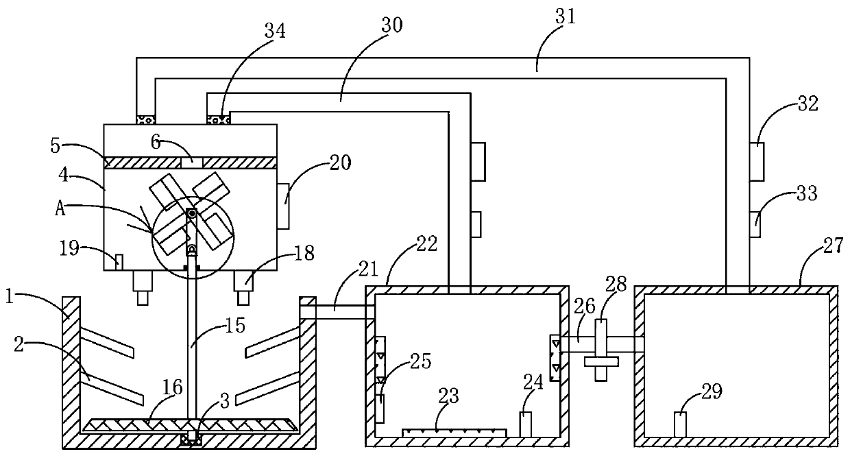
[0032] The following will clearly and completely describe the technical solutions in the embodiments of the present invention with reference to the accompanying drawings in the embodiments of the present invention. Obviously, the described embodiments are only some, not all, embodiments of the present invention. Based on the embodiments of the present invention, all other embodiments obtained by persons of ordinary skill in the art without making creative efforts belong to the protection scope of the present invention.

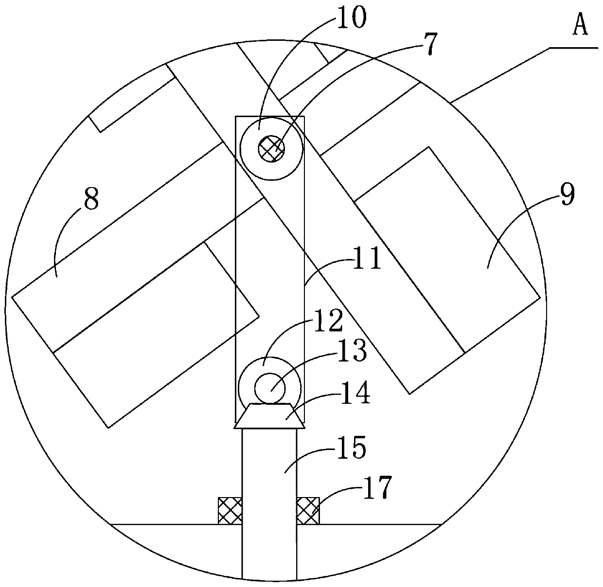
[0033] see Figure 1-2 , the present invention provides a technical solution:

[0034]A workpiece quenching equipment, comprising a quenching pool 1, a quenching liquid tank 4 is arranged above the quenching pool 1, a partition 5 is fixedly arranged in the inner cavity of the quenching liquid tank 4, a through hole 6 is opened on the partition 5, and the partition 5 is provided with a fixed shaft 7, the fixed shaft 7 is fixed between the inner walls of both e...


PUM


Abstract

The invention discloses workpiece quenching equipment and a process thereof. The workpiece quenching equipment comprises a quenching pond. A quenching liquid box is arranged above the quenching pond, a fixed shaft is arranged below a partition plate, two rotating rods are movably arranged on the fixed shaft, a driving gear is fixedly arranged at the center of one of the rotating rods, and the center of a driven bevel gear is fixedly connected to a bevel gear base through a transmission rod; the quenching pond communicates to a hot liquid box through a communicating pipe I, and the hot liquid box communicates to a cold liquid box through a communicating pie II; the hot liquid box communicates to the quenching liquid box through water return pipe I, and the cold liquid box communicates to the quenching liquid box through a water return pipe II. The invention provides the workpiece quenching equipment which can achieve a quenching effect of quickly cooling the workpiece at a high temperature and slowly cooling the workpiece at a low temperature, meets the latest research conclusion and improves the strength and hardness of the workpiece effectively. The invention also discloses the process based on the workpiece quenching equipment. The process is simple to operate, good in product quality and quite worth being popularized.

Description

technical field [0001] The invention relates to the field of quenching equipment, in particular to workpiece quenching equipment and a process thereof. Background technique [0002] In the prior art, the application number is "201810250814.9", a slewing bearing raceway without soft belt quenching equipment, which consists of a workbench, clamping parts, heating parts, agitator, quenching liquid, oil tank, adjustment mechanism, pneumatic mechanism, rotating It is composed of parts, lifting parts, control system and temperature measuring gun. The heating part uses multiple and evenly distributed sensors. The number and power of the sensors are determined according to the size of the workpiece. The gap between the sensor and the workpiece is adjusted by the adjustment mechanism. , the advance and retreat of the sensor is realized by a pneumatic mechanism, the workpiece and the worktable rotate together and move up and down, the rotating mechanism includes a motor, a transmissio...

Claims


Application Information

Patent Timeline
Patent Type & Authority Applications(China)
IPC IPC(8): C21D11/00C21D1/667
CPCC21D1/667C21D11/005
Inventor 胡文娜刘伟
Owner BENGBU COLLEGE
Why Eureka
Try Eureka