
Connecting structure for jacket foundation and underwater pile foundation of offshore wind turbine and grouting method

An offshore wind turbine and connection structure technology, applied in infrastructure engineering, construction, etc., can solve problems affecting the connection quality of jacket foundation pile feet and seabed piles, difficult to ensure the connection strength of jacket and piles, and difficult to control pile feet and seabed piles. Concentricity and other issues can prevent slurry leakage, avoid clogging of grouting ports, and ensure construction quality.

Active Publication Date: 2013-12-11
GUANGDONG MINGYANG WIND POWER IND GRP CO LTD
View PDF6 Cites 30 Cited by
  • Summary
  • Abstract
  • Description
  • Claims
  • Application Information

AI Technical Summary

Problems solved by technology

The current grouting process mainly has the following disadvantages. First, when the cement mortar is poured from the top of the jacket, the seawater in the cavity will dilute the prepared cement mortar, which is easy to form cavities, and it is difficult to ensure the connection strength between the jacket and the pile; Since the foundation of the wind turbine is smaller than that of the offshore platform, it is difficult to control the concentricity of the pile foot and the seabed pile when the jacket is inserted into the seabed pile, which will affect the connection quality between the pile foot of the jacket foundation and the seabed pile

Method used


Image

  • Connecting structure for jacket foundation and underwater pile foundation of offshore wind turbine and grouting method
  • Connecting structure for jacket foundation and underwater pile foundation of offshore wind turbine and grouting method

Examples


Embodiment Construction

[0022] The present invention will be further described in detail below in conjunction with the embodiments and the accompanying drawings, but the embodiments of the present invention are not limited thereto.

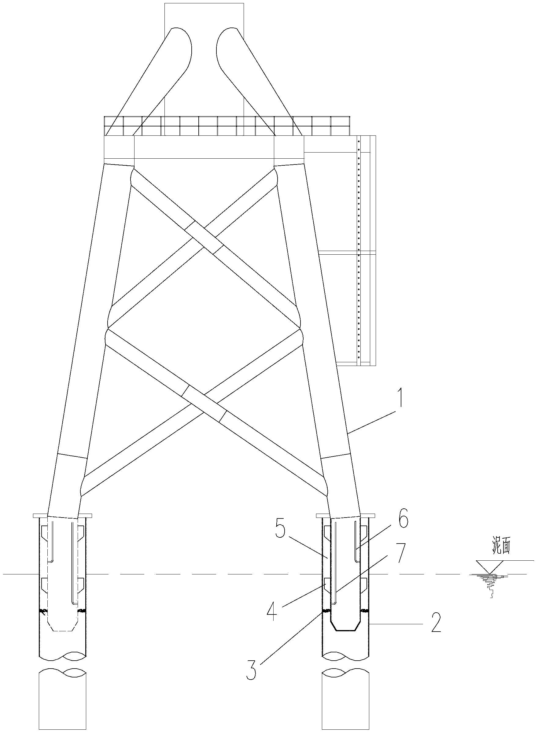
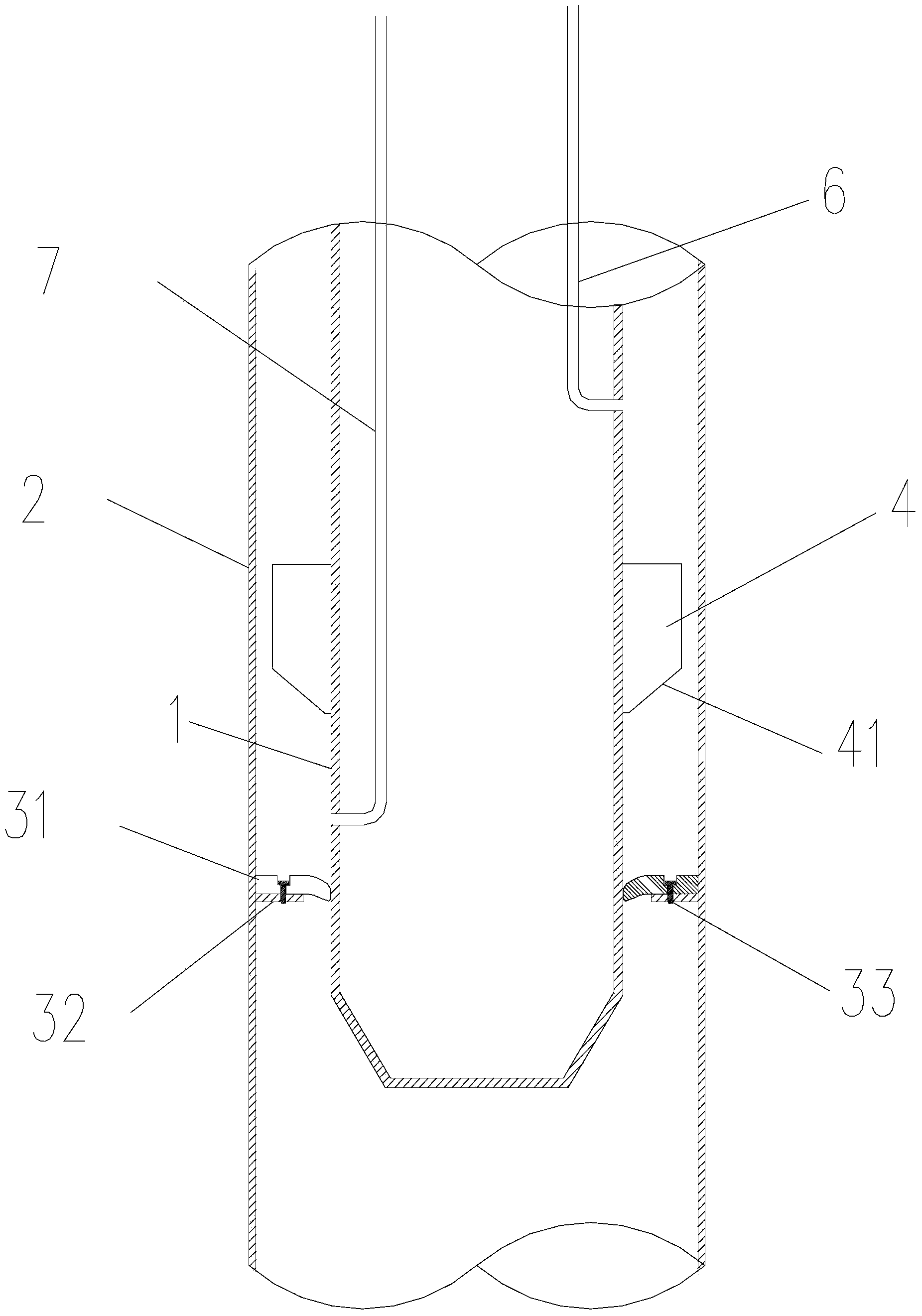
[0023] Such as figure 1 and figure 2 As shown, a connection structure between an offshore wind turbine jacket and a seabed pile foundation, including a cylindrical pile foot 1 on the wind turbine jacket foundation, and a tubular seabed pile 2, the pile foot 1 corresponds to the seabed pile 2 one by one, and the pile foot 1 is inserted through the nozzle of the upper end of the seabed pile 2 and suspended in the seabed pile 2, and there is an annular blocker 3 between the inner wall of the seabed pile 2 and the head where the pile foot 1 is inserted, the annular blocker 3, the pile foot 1 and the seabed The pile 2 forms an annular grouting cavity 5, and the grouting cavity 5 is filled with cement-based high-strength non-shrinkage grouting material (not shown in the figu...


PUM


Abstract

The invention discloses a connecting structure for a jacket foundation and an underwater pile foundation of an offshore wind turbine, which comprises column-shaped piles on the jacket foundation of the wind turbine and tubular underwater piles, the piles correspond to the underwater piles, and are inserted into the top orifices of the underwater piles and suspended in the underwater piles, an annular stopper is arranged between the inner wall of each underwater pile and the inserted head of each pile, an annular grouting cavity is defined by the annular stopper, the pile and the underwater pile, a high-position grouting tube and a low-position grouting tube are arranged in each pile, the wall of each pile is correspondingly provided with a high-position grouting orifice and a low-position grouting orifice which communicate with the grouting cavity, the high-position grouting tubes are connected with the high-position grouting orifices, and the low-position grouting tubes are connected with the low-position grouting orifices. The purpose of the invention is to provide the connecting structure for the jacket foundation and the underwater pile foundation of the offshore wind turbine and a grouting method in order to overcome the defects of conventional offshore platform grouting processes and adapt to the structural characteristics of offshore wind power foundations.

Description

technical field [0001] The invention relates to an offshore fan, in particular to a connection structure and a grouting method for an offshore fan jacket and a seabed pile foundation. Background technique [0002] In recent years, due to the increasing saturation of onshore wind power, offshore wind power has developed rapidly. Wind turbine foundation is an important part of offshore wind power construction. Since the seabed in the eastern offshore area of ​​my country is dominated by silty soft soil, the foundations of offshore wind turbines are mostly based on multi-pile caps, four-pile and six-pile jacket foundations. By grouting the annular space between the piles and the foot of the wind turbine foundation, Connect the wind turbine foundation with the pile. [0003] Offshore wind turbine foundations generally use steel pipe pile foundations, and the wind turbine tower is connected to the submarine pile foundation through the jacket foundation platform. The annular spa...

Claims


Application Information

Patent Timeline
IPC IPC(8): E02D27/42E02D27/44E02D27/52E02D15/04E02D15/06
Inventor 朱荣华陈达胜李少清董鹏张美阳
Owner GUANGDONG MINGYANG WIND POWER IND GRP CO LTD
Learn More