Check patentability & draft patents in minutes with Patsnap Eureka AI!

A heat exchanger and its header assembly

A technology of heat exchangers and headers, applied in the field of heat exchange, can solve the problems of reduced heat exchange efficiency of heat exchangers, uneven distribution of refrigerants, uneven distribution of refrigerants, etc., to improve heat exchange efficiency, shorten the falling stroke, Slow down the effect of gas-liquid separation

Active Publication Date: 2016-08-24
SANHUA(HANGZHOU) MICRO CHANNEL HEAT EXCHANGER CO LTD
View PDF5 Cites 0 Cited by
  • Summary
  • Abstract
  • Description
  • Claims
  • Application Information

AI Technical Summary

Problems solved by technology

However, in actual use, the state of the refrigerant at the inlet of the heat exchanger is a gas-liquid two-phase state. Due to the large difference in density between the gas and liquid phase refrigerants, gas-liquid separation will occur under the action of gravity, which will cause the refrigerant to be in a heat exchange state. The uneven distribution in the tube 3', especially for the vertically placed heat exchanger, the gas-liquid separation phenomenon is more serious, resulting in a greatly reduced heat exchange efficiency of the heat exchanger; after the cold medium enters the header, due to the And the influence of the resistance of the heat exchange tube 3' will also cause the uneven distribution of the refrigerant in the heat exchange tube 3'

Method used


Image

  • A heat exchanger and its header assembly
  • A heat exchanger and its header assembly
  • A heat exchanger and its header assembly

Examples


Embodiment Construction

[0033] The core of the present invention is to provide a header assembly, and the heat exchanger using the header assembly has higher heat exchange efficiency. Another core of the present invention is to provide a heat exchanger having the above-mentioned header assembly.

[0034] Without loss of generality, this article takes the application of the header assembly in the evaporator heat exchanger as an example to introduce the technical solution. Those skilled in the art should understand that the header assembly described herein can also be applied to other types of heat exchangers. in the heat exchanger.

[0035] In order to enable those skilled in the art to better understand the technical solutions of the present invention, the present invention will be further described in detail below in conjunction with the accompanying drawings and specific embodiments.

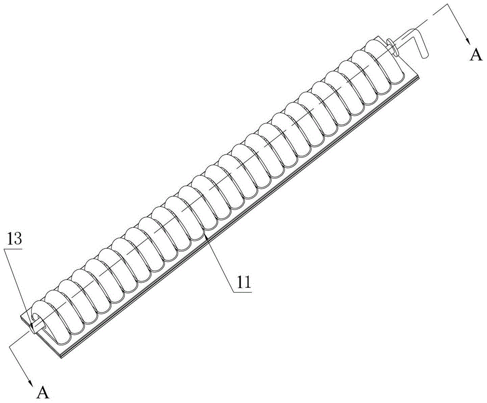
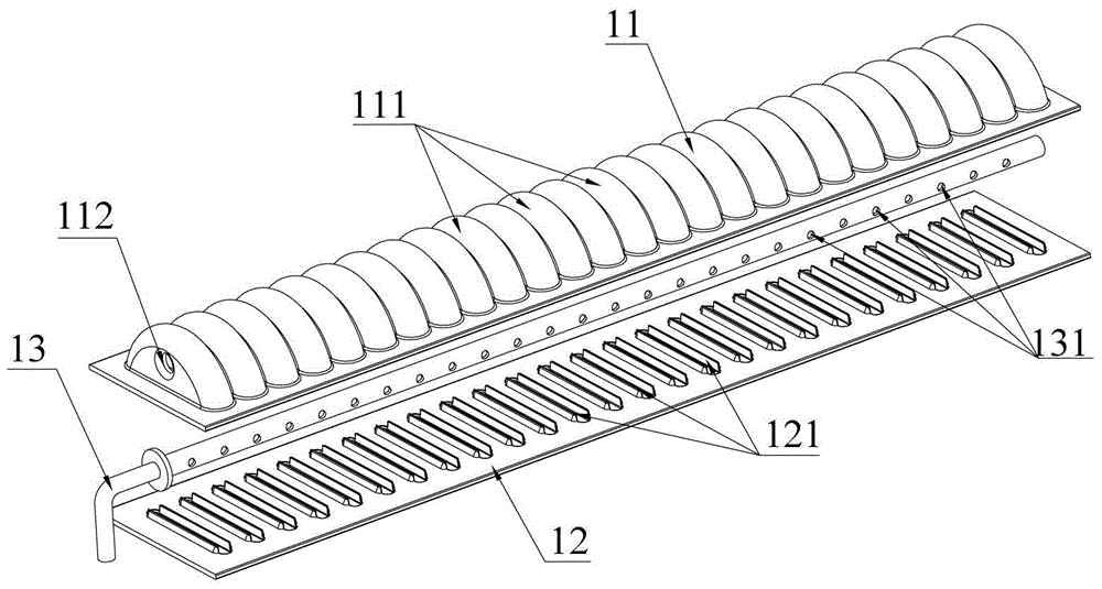
[0036] Please refer to Figure 2 to Figure 4 , figure 2 It is a schematic structural diagram of a header assem...


PUM


Abstract

The invention discloses a heat exchanger and a collecting pipe assembly of the heat exchanger. The collecting pipe assembly comprises a collecting pipe body, wherein a plurality of heat exchange tube insertion holes are axially formed in the collecting pipe body, the inner cavity of the collecting pipe body is axially divided into a plurality of independent chambers respectively and correspondingly communicated with the heat exchange tube insertion holes, the independent chambers are communicated with at least one heat exchange tube insertion hole, each independent chamber is communicated with an external heat exchange medium through corresponding pipelines, the pipelines are respectively communicated with the independent chambers, and the independent chambers are communicated with heat exchange tubes inserted into the heat exchange tube insertion holes in the independent chambers. Each independent chamber of the cavity of the collecting pipe body is small in space area, so that the falling route of the heat exchange medium from a channel inlet to the inner part of the inner is greatly shortened, and a gas-liquid separation phenomenon caused due to gravity action during the falling process of the heat exchange medium is slowed down; furthermore, the heat exchange medium does not need to be distributed from bottom to top after flowing into the independent chambers, so that the heat exchange medium in each heat exchange tube can be uniformly distributed, and the heat exchange efficiency of the heat exchanger is increased.

Description

technical field [0001] The invention relates to the technical field of heat exchange, in particular to a heat exchanger and a header assembly thereof. Background technique [0002] A heat exchanger is a device that realizes heat transfer between cold and hot fluids, and is widely used in HVAC and other fields. [0003] Please refer to figure 1 , figure 1 It is a structural schematic diagram of a typical heat exchanger in the prior art. [0004] A typical heat exchanger includes two headers parallel to each other, and between the two headers there are a plurality of substantially parallel heat exchange tubes 3', and between adjacent heat exchange tubes 3' there are Corrugated fins 2'. The two headers are provided with a plurality of heat exchange interfaces on the corresponding tube walls along the length direction, and the two ends of the heat exchange tube 3' are respectively inserted into the heat exchange interfaces on the headers to realize the two collectors. The f...

Claims


Application Information

Patent Timeline
Patent Type & Authority Patents(China)
IPC IPC(8): F28F9/02F28F9/22
Inventor 崔凯
Owner SANHUA(HANGZHOU) MICRO CHANNEL HEAT EXCHANGER CO LTD
Features
  • R&D
  • Intellectual Property
  • Life Sciences
  • Materials
  • Tech Scout
  • Unparalleled Data Quality
  • Higher Quality Content
  • 60% Fewer Hallucinations
Learn More