Device and method for imaging detecting of soil mass sample micro-deformation

An imaging detection and micro-deformation technology, applied in measuring devices, optical devices, instruments, etc., can solve problems such as poor soil sample micro-deformation measurement effect, incompetence of imaging system for micro-deformation analysis, and image image motion blur.

Active Publication Date: 2013-12-11
SOUTHWEST JIAOTONG UNIV
View PDF9 Cites 15 Cited by
  • Summary
  • Abstract
  • Description
  • Claims
  • Application Information

AI Technical Summary

Problems solved by technology

But this method has defects: in the centrifuge test, the camera system is fixed on the concrete roof of the centrifuge room, the model box 2 at the end of the centrifuge arm is in a state of circular motion, and the imaging system fixed on the concrete roof and the arm The model box is working in the relative motion mode, and the resulting image has image motion blur
However, the imaging device described in this patent has a poor measurement effect on soil sample micro-deformation
Since the model deformation of the geotechnical centrifuge 1 is 1 / 60 of the actual deformation on site, that is to say, the model deformation must be multiplied by 60 to obtain the on-site deformation. The imaging system of the device described in this patent cannot be used for micro-deformation analysis. need

Method used


Image

  • Device and method for imaging detecting of soil mass sample micro-deformation
  • Device and method for imaging detecting of soil mass sample micro-deformation
  • Device and method for imaging detecting of soil mass sample micro-deformation

Examples


specific Embodiment approach

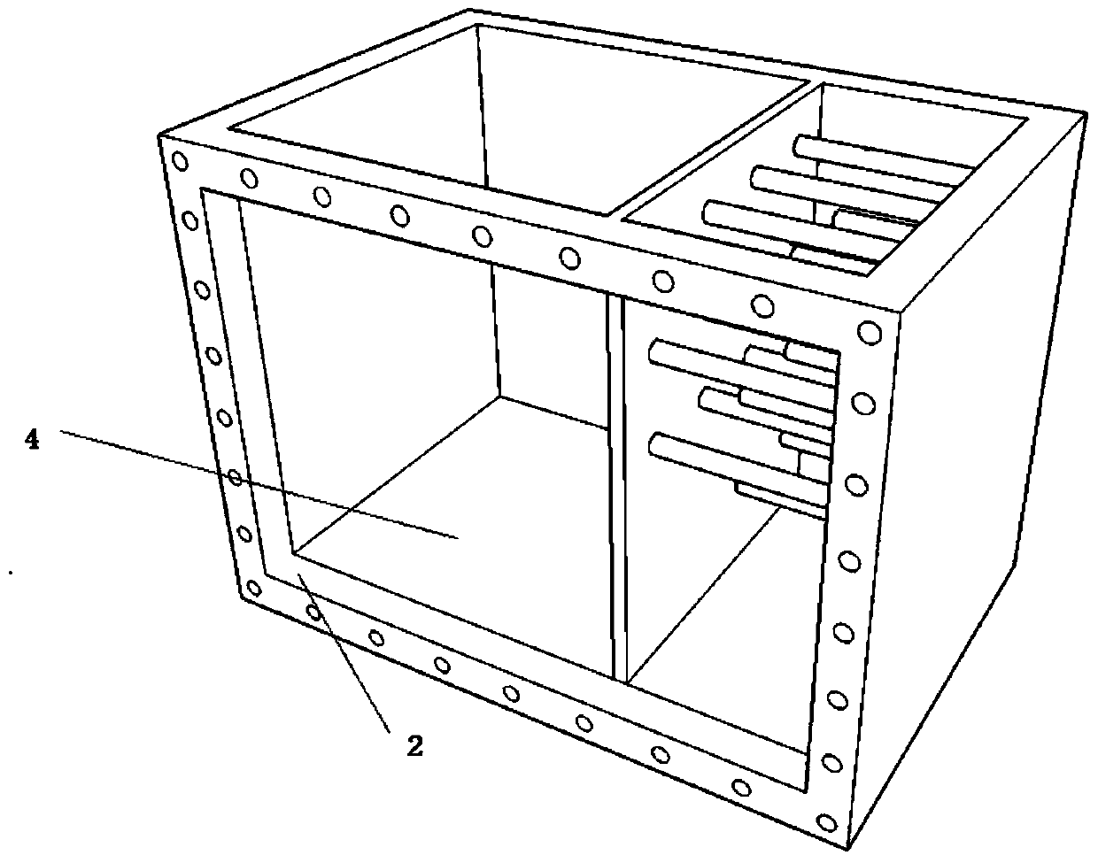
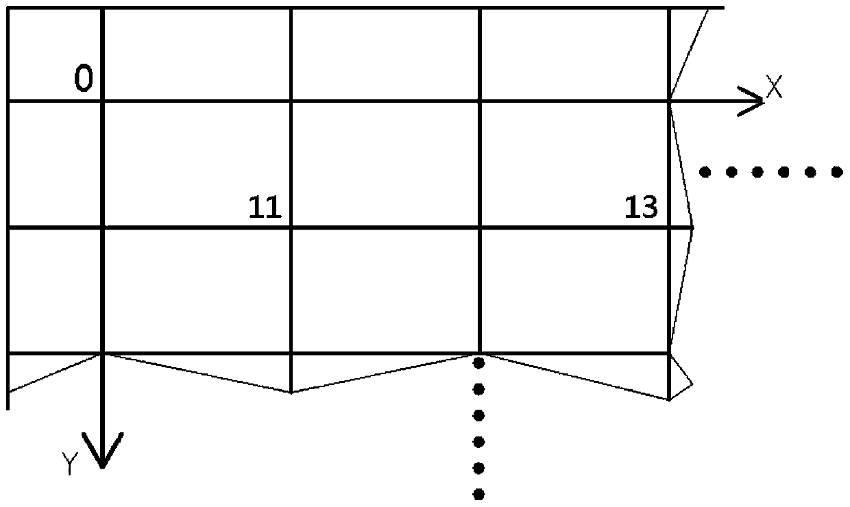
[0038] The fixed reference coordinate grid density of the inner surface 44 of the plexiglass of the model box 2 is designed according to a 135 full-frame camera. The horizontal direction of the fixed reference coordinate grid corresponds to the long side of the image CCD array, that is, the side with a length of 26mm, and the grid spacing in the horizontal direction is 12mm, which is recorded as a row and represented by x; the vertical direction of the fixed reference coordinate grid corresponds to the image CCD array The short side, that is, the side with a length of 24mm, and a grid spacing of 8mm in the vertical direction, is recorded as a column and represented by y. The method of labeling the edge intersections of the vertical and horizontal cross lines of the fixed reference coordinate grid adopts alternate rows and columns to label according to serial numbers, such as image 3 As shown, 13 means the first row and third column, that is, the coordinates are 1,3. Select t...


PUM


Abstract

The invention relates to sample micro-deformation measuring of the geotechnical test field, in particular to soil mass sample micro-deformation measuring of a geotechnical centrifuge, and discloses a device for imaging detecting of soil mass sample micro-deformation. The device comprises the geotechnical centrifuge, a camera system is fixed on the outer side of a model casing of the geotechnical centrifuge, soil mass samples are contained in the model casing, and a fixing grid reference net is arranged on the inner side face of organic glass of a transparence window of the model casing. The invention further discloses a method for imaging detecting on the soil mass samples by utilizing the device for imaging detecting of the soil mass sample micro-deformation.

Description

technical field [0001] The invention relates to the micro-deformation measurement of samples in the field of geotechnical testing, in particular to the micro-deformation measurement of soil samples of geotechnical centrifuges. Background technique [0002] The geotechnical centrifuge is a large-scale indoor test equipment that simulates the deformation of the soil caused by the stress of the geotechnical work site. The acting force on the soil in the model box comes from the centrifugal force generated when the centrifuge rotates. The speed of the centrifuge is directly proportional to the centrifugal force, and the speed of the centrifuge is adjusted by the control system to reach the pressure required for the model soil test. [0003] The large geotechnical centrifuge consists of a rotating arm, a column connected to the rotating arm, a model box at one end of the rotating arm, a counterweight box at the other end, and a drive and control system. During operation, the su...

Claims


Application Information

Patent Timeline
Patent Type & Authority Applications(China)
IPC IPC(8): G01B11/16
Inventor 秦军
Owner SOUTHWEST JIAOTONG UNIV
Why Eureka
Try Eureka