A boundary location method for non-ideal iris images

An iris image and positioning method technology, which is applied to instruments, character and pattern recognition, computer parts and other directions, can solve problems such as large amount of calculation, difficult and accurate iris boundary positioning, and deterioration of recognition effect.

Inactive Publication Date: 2016-12-28
SHANDONG NORMAL UNIV
View PDF1 Cites 0 Cited by
  • Summary
  • Abstract
  • Description
  • Claims
  • Application Information

AI Technical Summary

Problems solved by technology

For example, the calculus operator method of Daugman et al. [JDaugman.How iris recognition works[J].IEEE Trans.Circuits and Systems for Video Technology,2004,14(1):21-30.] is the most widely used, but especially in interference Under the influence of light changes, it is difficult to accurately locate the iris boundary
[0004] In the non-ideal acquisition environment, due to the interference of environmental factors, the quality of the iris image is often affected, which seriously deteriorates the recognition effect
For example, the iris boundary location method based on the Hough transform needs to search the radius of the transformation center, which is computationally intensive and susceptible to noise and other disturbances

Method used


Image

  • A boundary location method for non-ideal iris images
  • A boundary location method for non-ideal iris images
  • A boundary location method for non-ideal iris images

Examples


Embodiment Construction

[0059] The present invention will be further described below in conjunction with the accompanying drawings and embodiments.

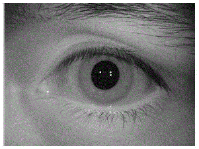
[0060] The iris image collected in the near-infrared band and only includes the eye area is stored in the computer in a common format (such as bmp, jpg, tiff, etc.), and the algorithm is called for processing, and then the processing result can be displayed with the image recognition software.

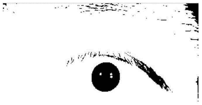
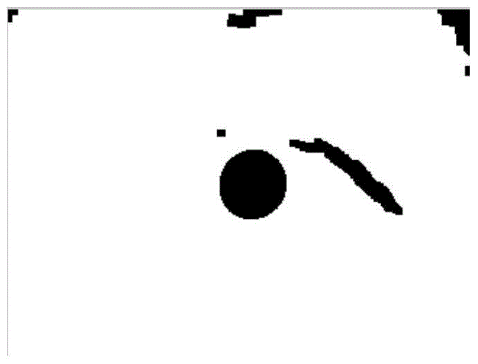
[0061] A boundary location method for non-ideal iris images, which mainly includes two parts: inner boundary location and outer boundary location, such as Figure 9 As shown, the internal boundary positioning process includes 5 steps, which are respectively: 11) binarization operation of the iris image, 12) searching for the reference point C inside the pupil, 13) boundary detection, 14) selecting the effective area, 15 ) based on the inner boundary positioning of the improved Hough transform; such as Figure 10 As shown, the outer boundary positioning process ...


PUM


Abstract

The invention discloses a method for locating boundaries of a non-ideal iris image. The method for locating the boundaries of the non-ideal iris image mainly comprises the steps of inner boundary location and outer boundary location. The inner boundary locating process comprises the steps that 11) binarization operation of the iris image is conducted, 12) a datum point inside each pupil is searched, 13) the boundaries are detected, 14) an effective area is selected, and 15) the inner boundary is located on the basis of improved Hough transformation. The outer boundary locating process comprises the steps that 21) the binarization of the iris image is achieved through a three-threshold value, 22) an effective area is selected, and 23) the outer inner boundary is located through improved Hough transformation. The method for locating the boundaries of the non-ideal iris image has the advantages that the efficiency and the accuracy of boundary location of the non-ideal collected iris image are improved.

Description

technical field [0001] The invention relates to a border location method for non-ideal iris images. Background technique [0002] With the rapid development of information technology and computer technology, the importance of information security has become more and more prominent. In view of the problems existing in traditional identification technology, biometric identification technology is more and more applied to people's daily life and work. At present, biometric recognition is widely used, such as face, iris, fingerprint, voice, vein, etc., and iris recognition has the advantages of high stability, uniqueness and anti-invasion, and has been widely used in security, mining, finance and other fields. Application has become the mainstream biometric technology in the future [Biometrics: a tool for information security [J]. IEEE Trans. Information Forensics and Security, 2006, 1(2), 125-143. A K Keene, A Ross, S Ponca Di. Biometric Identification: An Information Security...

Claims


Application Information

Patent Timeline
Patent Type & Authority Patents(China)
IPC IPC(8): G06K9/00G06K9/32
Inventor 万洪林韩民张国裕
Owner SHANDONG NORMAL UNIV
Why Eureka
Try Eureka