LCD foreign body defect detection method

A defect detection and foreign matter technology, applied in the field of LCD defect detection, can solve problems such as mura defect detection interference

Active Publication Date: 2013-12-11
NANJING UNIV
View PDF4 Cites 37 Cited by
  • Summary
  • Abstract
  • Description
  • Claims
  • Application Information

AI Technical Summary

Problems solved by technology

The acquired LCD picture detection is often affected by the factors of light texture,

Method used


Image

  • LCD foreign body defect detection method
  • LCD foreign body defect detection method
  • LCD foreign body defect detection method

Examples


Embodiment

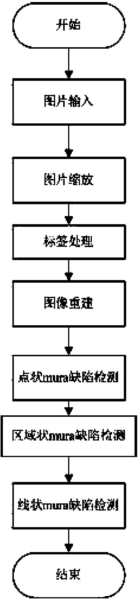
[0099] This embodiment includes the following parts:

[0100] 1. Image scaling specifically includes the following steps:

[0101] First use the 9*9 template to apply mean filtering to the original image,

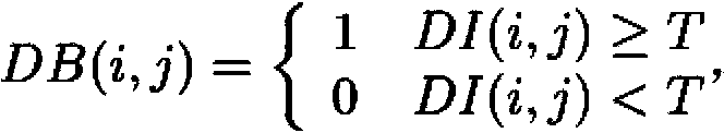
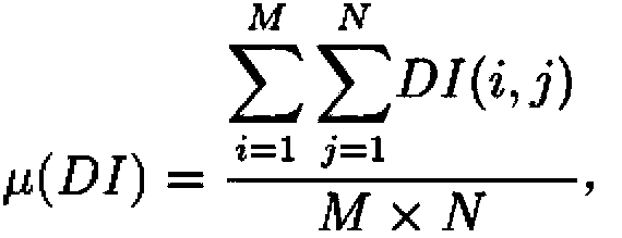
[0102] If ( i , j ) = Σ u = i - s i + s Σ v = j - s j + s I ( u , v ) ...


PUM


Abstract

The invention discloses an LCD foreign body defect detection method. The LCD foreign body defect detection method comprises the following steps of image resizing, namely, image resizing is carried out according to a bilinear interpolation algorithm, label detection, namely, the position of a label is detected and the label is eliminated to obtain an image OI, (3)image reconstruction, namely, the image OI is reconstructed through a singular value decomposition method to obtain a reconstructed image CI and the reconstructed image CI is subtracted from the image OI to obtain a difference image DI, (4), point-shaped foreign body defect detection, namely, thresholding defect cutting is conducted on the obtained difference image DI, outline number statistics is carried out through outline detection, total defect area is calculated, and whether point-shaped foreign body defects exist or not is judged, (5) region-shaped foreign body defect detection, namely, the difference image DI is divided into num windows, region foreign body defect detection is conducted on each window, and average gray value and variance statistics of each window is carried out, (6) line-shaped foreign body defect detection, namely, edge detection is conducted on the difference image DI according to an edge detection algorithm to judge whether line-shaped foreign body defects exist or not.

Description

technical field [0001] The invention relates to the field of LCD defect detection, in particular to an LCD foreign matter (mura) defect detection method. Background technique [0002] In recent years, with the advancement of technology, the rate of good products has continued to increase, and LCD displays have flourished and can be seen everywhere and have completely replaced the bulky CRT displays and occupied the display market. In particular, TFT-LCD (Thin Film Transistor), that is, thin film field effect transistor liquid crystal display, is currently the only display device that has fully caught up with and surpassed CRT in terms of brightness, contrast, power consumption, life, volume and weight. As the liquid crystal display market is booming, people pay more and more attention to the liquid crystal display industry, and testing, as an indispensable part of the production process, has also attracted the attention of many researchers at home and abroad. In order to re...

Claims


Application Information

Patent Timeline
IPC IPC(8): G06T7/00
Inventor 杨育彬高阳赵九洋
Owner NANJING UNIV
Why Eureka
Try Eureka