Diaphragm, filter plates, and filter press dehydrator

A filter press dehydration and filter plate technology, applied in the fields of diaphragms, filter plates and filter press dehydrators, can solve the problems of increased number of components, poor durability, easy damage, etc. The effect of spraying with pressurized water and easy processing

Active Publication Date: 2013-12-11
KUBOTA LTD
View PDF9 Cites 3 Cited by
  • Summary
  • Abstract
  • Description
  • Claims
  • Application Information

AI Technical Summary

Problems solved by technology

[0011] However, in the diaphragm 60 described above, repeated stress is generated in the movable part 65 every time the expansion and contraction of the diaphragm 60 are repeated in the extrusion process.
Since the movable part 65 is in contact with the filter plate 70, a large stress is concentrated, and wear occurs every time the extrusion dehydration operation is performed, so there are problems in that the durability deteriorates and the filter plate 70 is easily damaged.
As a result, there are problems in that the number of components increases and the number of manufacturing processes increases.

Method used


Image

  • Diaphragm, filter plates, and filter press dehydrator
  • Diaphragm, filter plates, and filter press dehydrator
  • Diaphragm, filter plates, and filter press dehydrator

Examples


Embodiment Construction

[0101] The diaphragm, filter plate and filter press dehydrator of the present invention will be described below.

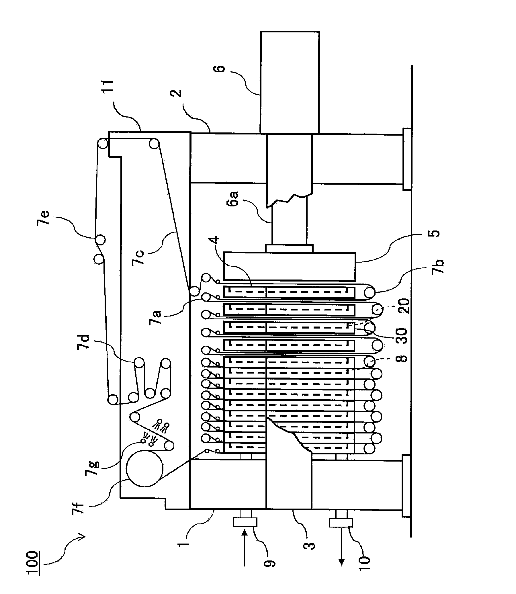
[0102] Such as figure 1 As shown, in the filter press dewatering machine 100, a pair of guide rails 3 are horizontally mounted between the left frame 1 and the right frame 2, and a pair of guide rails 3 are placed on the pair of guide rails 3 to be able to slide between the left frame 1 and the right frame 2. Multiple filter units 4. A pressing cylinder 6 is provided on the right frame 2 , and a pressing member 5 is provided at the tip of a rod member 6 a of the pressing cylinder 6 .

[0103] A plurality of filter units 4 are connected to respective adjacent filter units 4 with link members (not shown), figure 1 The filter unit 4 at the middle right end is connected with the filter unit driving device, and the filter unit 4 at the left end is connected with the left frame 1 side. When the filter unit 4 at the right end moves to the right, the filter units 4 s...


PUM


Abstract

Provided are a diaphragm which has a decreased chance of being damage, filter plates which are easily processed, and a filter press dehydrator upon which a filter chamber is formed by the diaphragm and the filter plates. The filter chamber (8) is formed by: the diaphragm (20) in which a thick section (21) that functions as a filter frame is integrally formed at the periphery of a thin section (22) that compresses an undiluted solution; and the filter plates, on side of which a compression section (31) that compresses the diaphragm (20) between adjacent filter plates is formed, and on the other side of which a rising section (37), into which the diaphragm (20) can be inserted, and the thickness of which is smaller than that of the thick section (21), is formed. By supplying the undiluted solution to the filter chamber (8) and inflating the diaphragm (20), the undiluted solution is compressed and dehydrated, producing a cake. In this case, the thick section (21) of the diaphragm (20) functions as a seal surface.

Description

technical field [0001] The invention relates to a diaphragm assembled in a filter press dehydrator, which supplies and squeezes raw liquid to a filter chamber divided by a filter frame and a filter plate. Background technique [0002] Conventionally, filter press dehydrators have been widely used as dehydrators for solid-liquid separation in product manufacturing processes such as carbon production and titanium production, and sludge treatment processes. [0003] The filter press dehydration mechanism is such that a filter chamber is formed between the side-by-side filter plates and diaphragms, the solid-liquid separation is performed through the filter cloth suspended in front of the filter plates and diaphragms, and the dehydration filter formed in the filter chamber is squeezed by the diaphragm. cake. [0004] Patent Document 1 proposes an example of a filter plate and a diaphragm used in such a filter press dehydrator. Such as Figure 12 As shown in (a), Patent Documen...

Claims


Application Information

Patent Timeline
Patent Type & Authority Applications(China)
IPC IPC(8): B01D25/12
CPCB01D25/215B01D25/127B01D25/285
Inventor 水谷太杉村裕康辻野博
Owner KUBOTA LTD
Why Eureka
Try Eureka